Special Tools
J 45059 Angle Meter
- Install the upper crankshaft main bearings into the block.
- Lubricate the upper crankshaft main bearing surface with clean engine oil.
- Install the crankshaft.
- Install the lower crankshaft main bearings into the main bearing caps.
- Lubricate the lower crankshaft main bearing surface with clean engine oil.
- Install the crankshaft main bearing caps.
- Install the crankshaft main bearing cap stiffener.
- Install new crankshaft main bearing bolts. Start the crankshaft main bearing cap bolts by hand. Ensure the bottom of the crankshaft main bearing cap is parallel to the block surface.
- Tighten the crankshaft main bearing cap bolts in equal increments.
- Tighten the crankshaft main bearing cap bolts to 25 N·m (18 lb ft) in sequence.
- Use J 45059 to tighten the crankshaft main bearing cap bolts an additional 180 degrees.
- Measure the crankshaft end play.
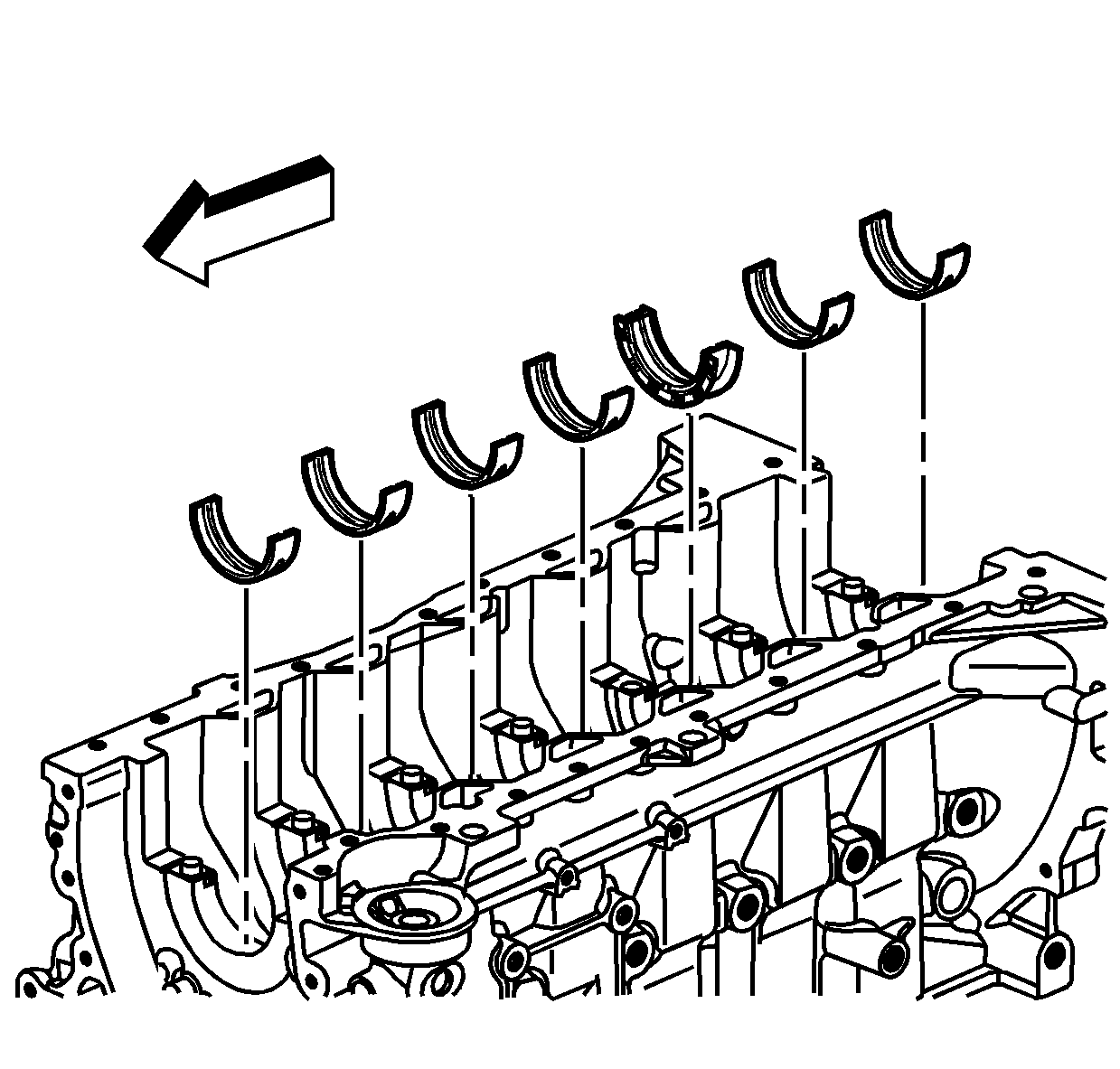
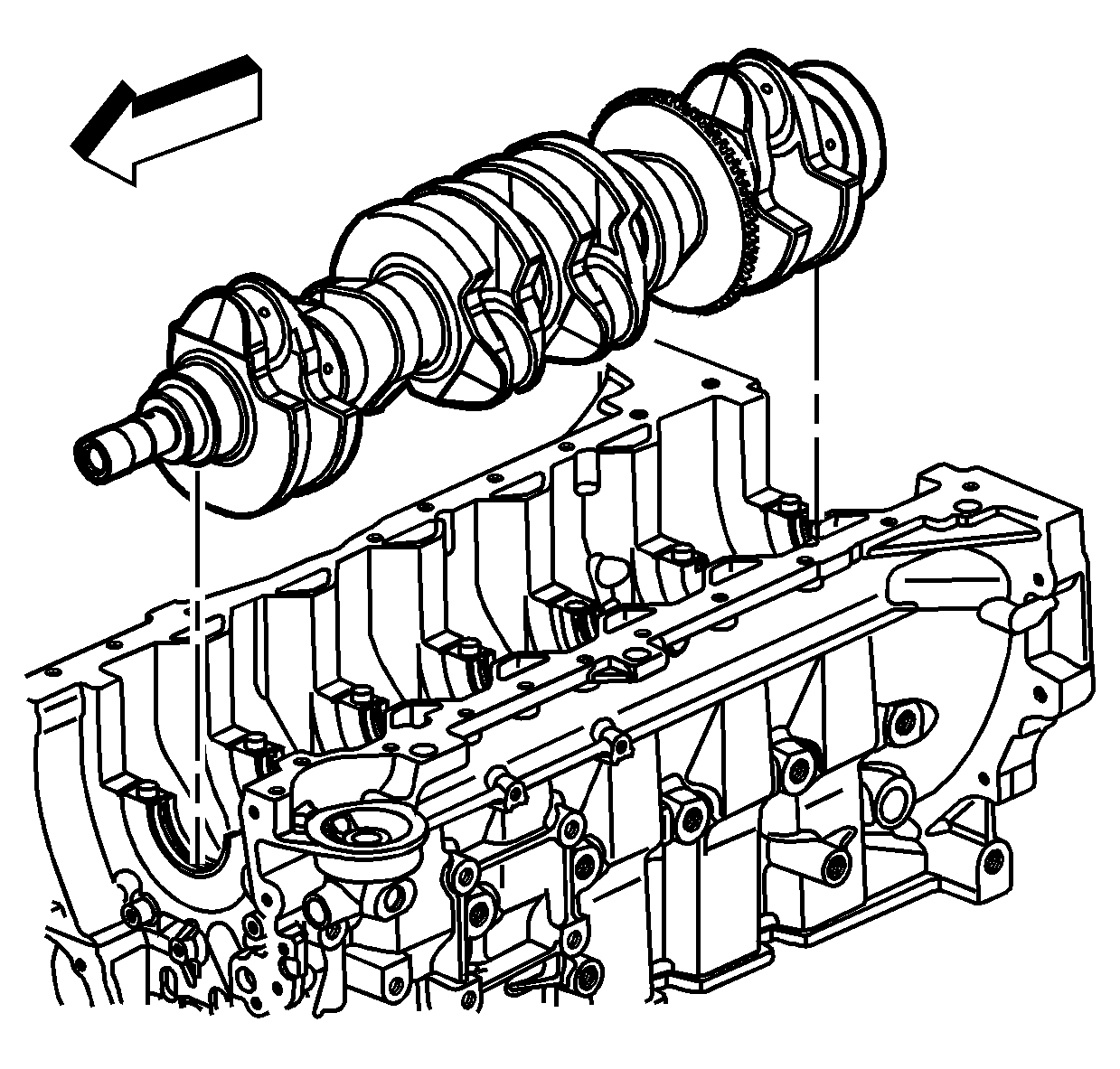
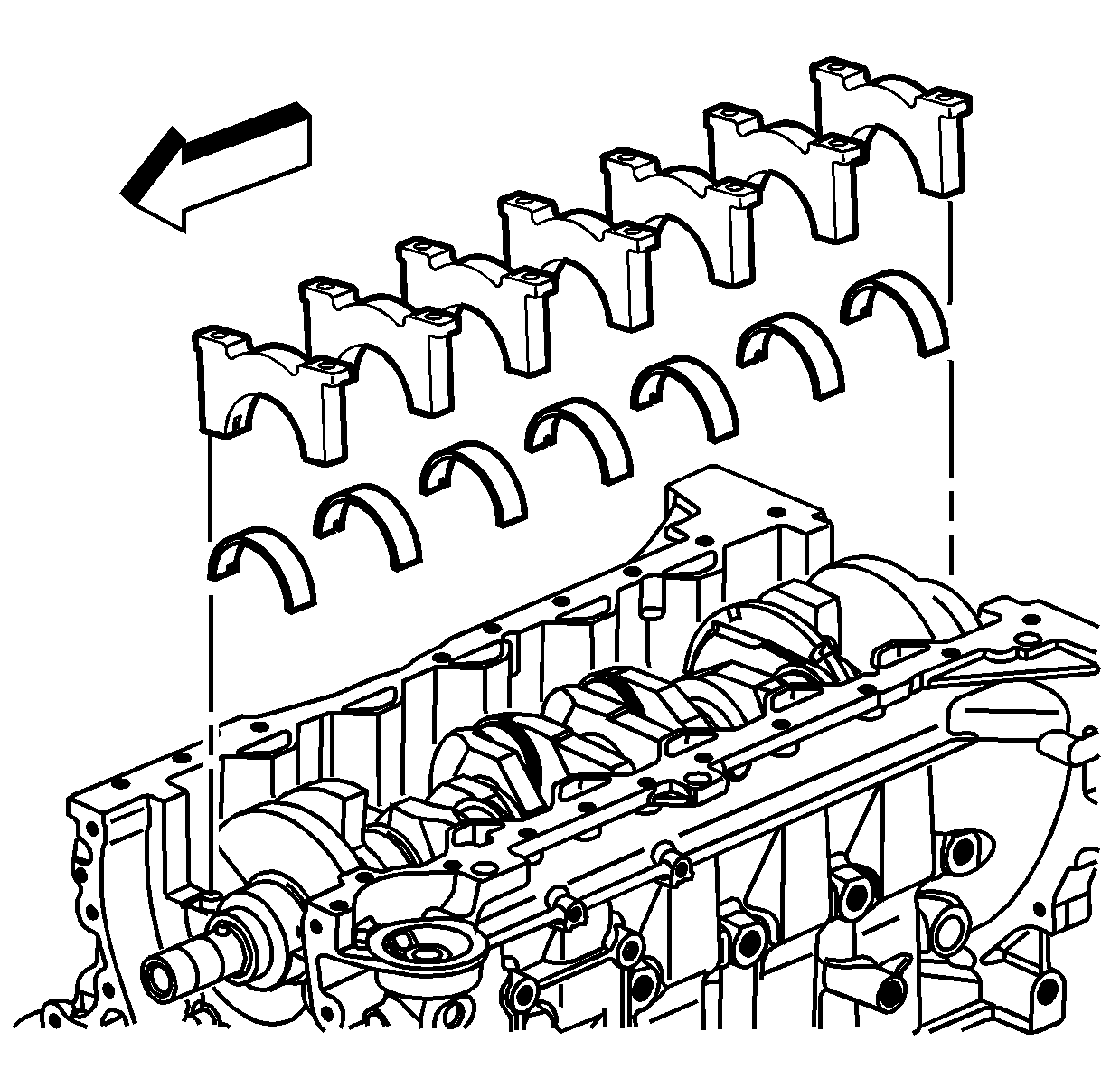
Important: Refer to the pin stamp on the crankshaft main bearing caps for sequence and direction of installation. The pin stamp arrow points to the front of the engine.
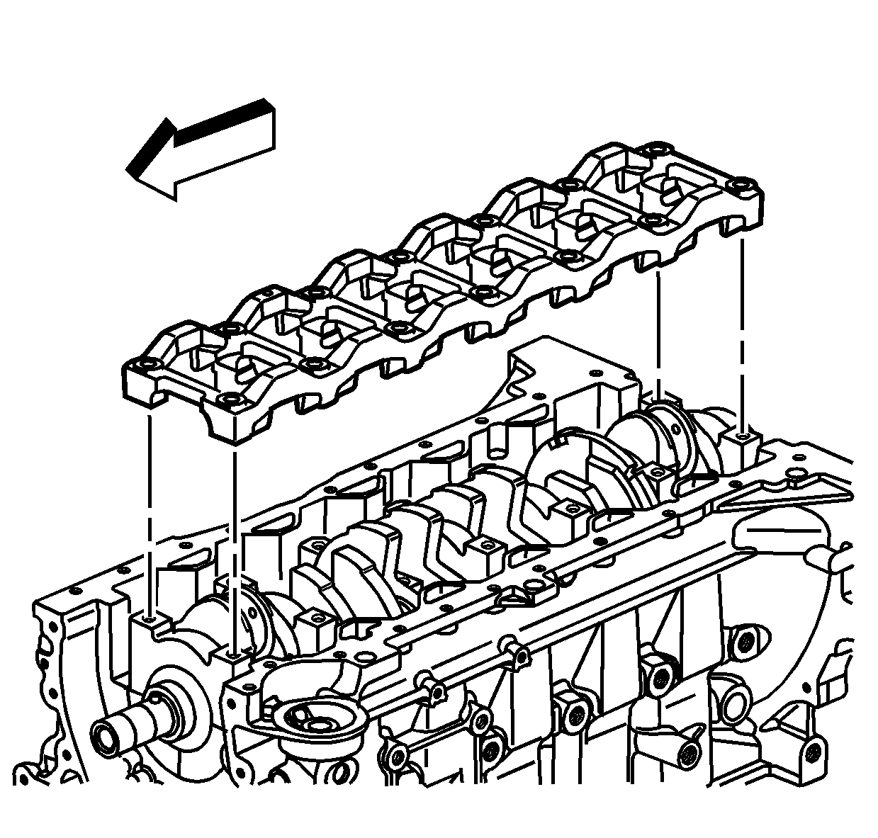
Important: The crankshaft main bearing cap stiffener is directional. The end marked front goes to the front.
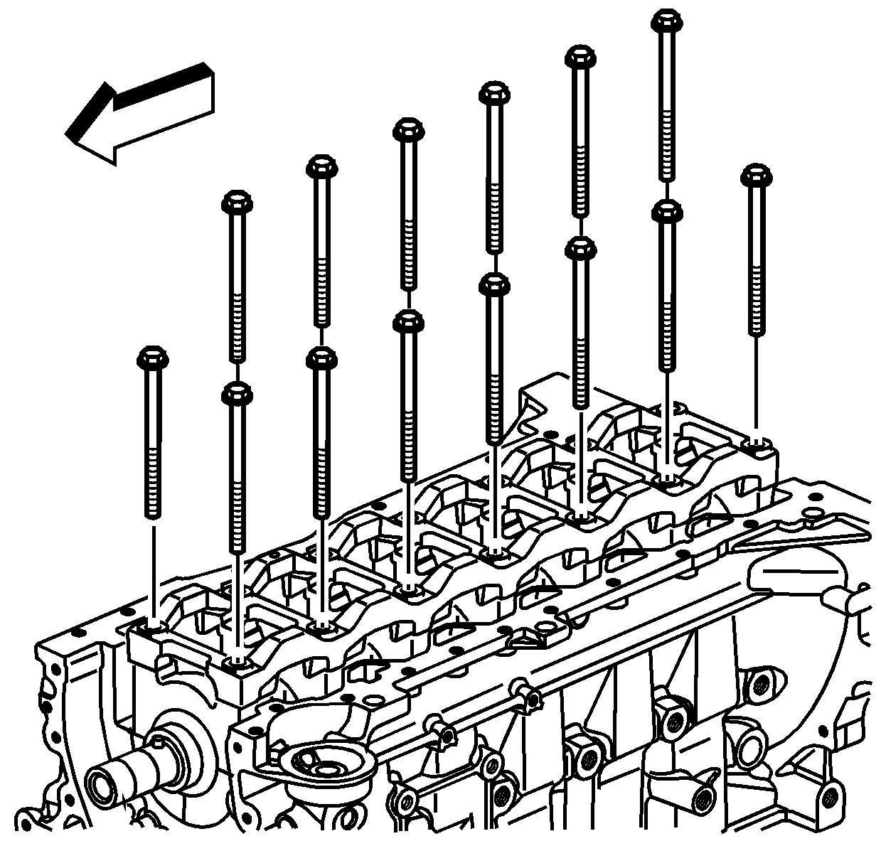
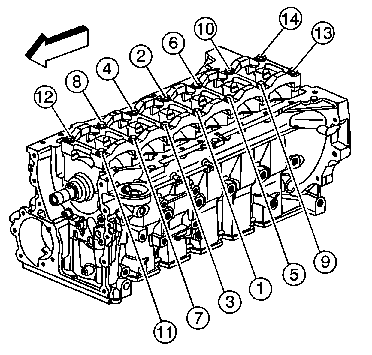
Notice: Use the correct fastener in the correct location. Replacement fasteners must be the correct part number for that application. Fasteners requiring replacement or fasteners requiring the use of thread locking compound or sealant are identified in the service procedure. Do not use paints, lubricants, or corrosion inhibitors on fasteners or fastener joint surfaces unless specified. These coatings affect fastener torque and joint clamping force and may damage the fastener. Use the correct tightening sequence and specifications when installing fasteners in order to avoid damage to parts and systems.
Tighten
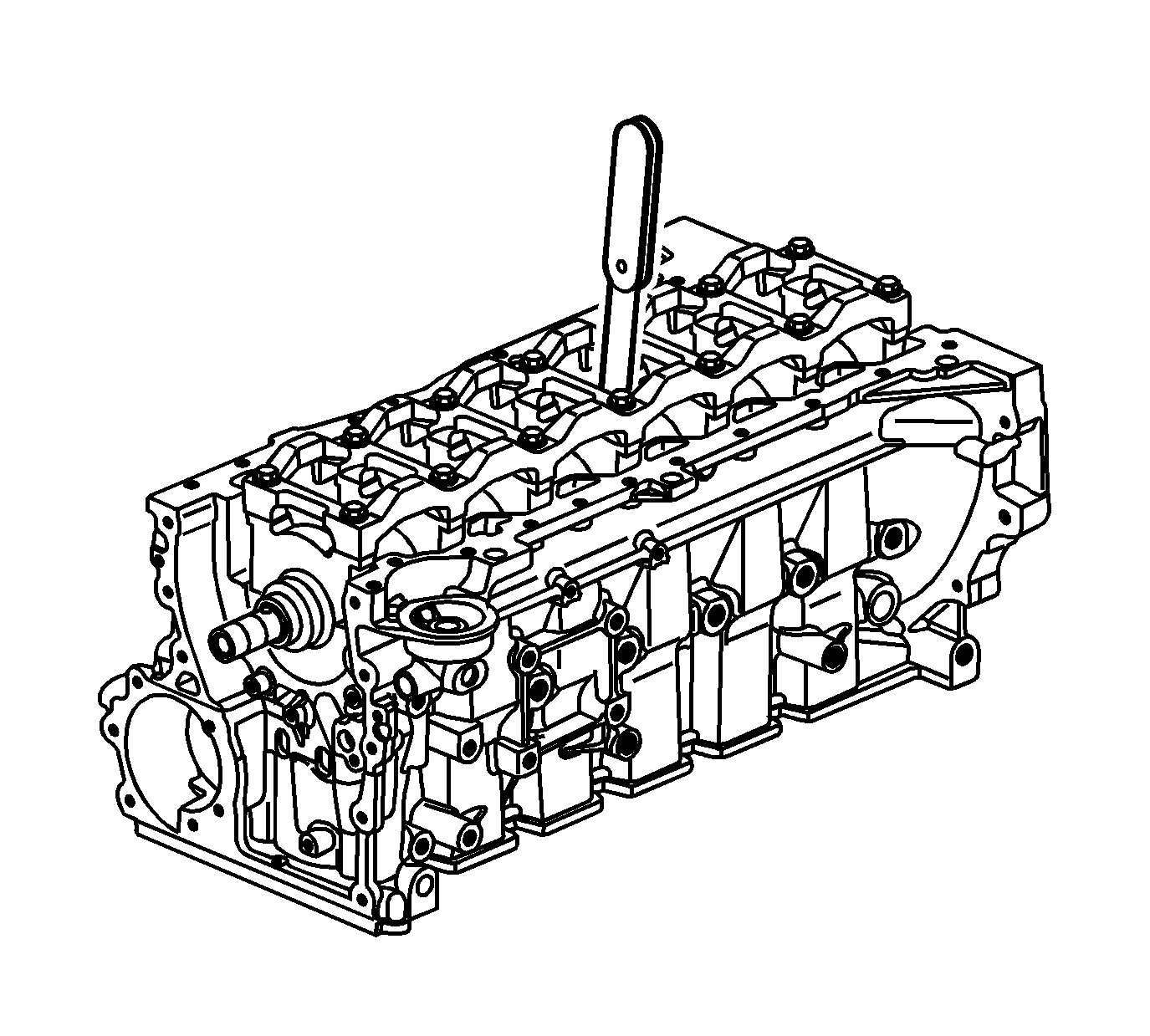
| 10.1. | Thrust the crankshaft forward or rearward. |
| 10.2. | Insert a feeler gage between the thrust crankshaft bearing and the bearing surface of the crankshaft and measure the bearing clearance. Refer to Engine Mechanical Specifications for the proper clearance. |
| 10.3. | If the bearing clearance is not within specifications, inspect the thrust surfaces for nicks, gouges or raised metal. Minor imperfections may be removed with a fine stone. |
