- Remove the air cleaner element. Refer to
Air Cleaner Element Replacement.
- Remove the air cleaner outlet resonator. Refer to
Air Cleaner Outlet Resonator Replacement.
- Remove the powertrain control module (ECM) and engine wire harness bracket and related hoses and connections. Refer to
Engine Control Module Replacement.
- Remove the generator. Refer to
Generator Replacement.
- Remove the intake manifold. Refer to
Intake Manifold Replacement.
- Remove the exhaust manifold. Do not remove the exhaust pipe from the manifold. Only have the manifold pushed off to the side of the engine. Refer to
Exhaust Manifold Replacement.
- Position the A/C line out of the way towards the front of the vehicle.
- Disconnect the following cross-vehicle engine wiring harness connectors:
| • | Engine coolant temperature sensor |
| • | Manifold absolute pressure (MAP) sensor |
| • | Harness clamps at power steering pump |
| • | Wiring harness fastener at the right front inner fender |
| • | Heated oxygen sensor (HO2S) |
- Set aside the cross-vehicle engine wiring harness on the left side of the vehicle.
- Remove the camshaft cover. Refer to
Camshaft Cover Replacement.
- Partially drain the cooling system.
| 11.2. | Place an approved container under the thermostat housing. |
| | Note: Do not completely remove the thermostat housing. Complete removal of the thermostat housing will not provide steady drain path and will increase clean up time.
|
| 11.3. | Loosen the thermostat housing bolts and slowly pull the thermostat housing back away from the engine. This will allow for a steady drain path for coolant. |
| 11.4. | Once coolant is drained remove the thermostat housing bolts, thermostat housing, and thermostat. Inspect and replace as necessary. |
| 11.5. | Clean and inspect the O-ring. Replace as necessary. |
| 11.6. | Clean and inspect the sealing surface of the engine block. |
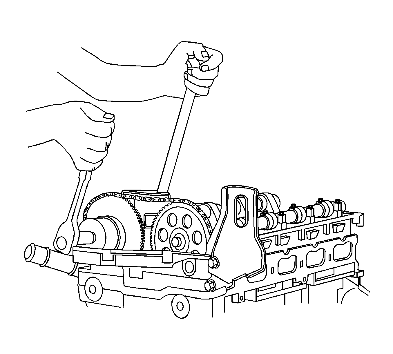
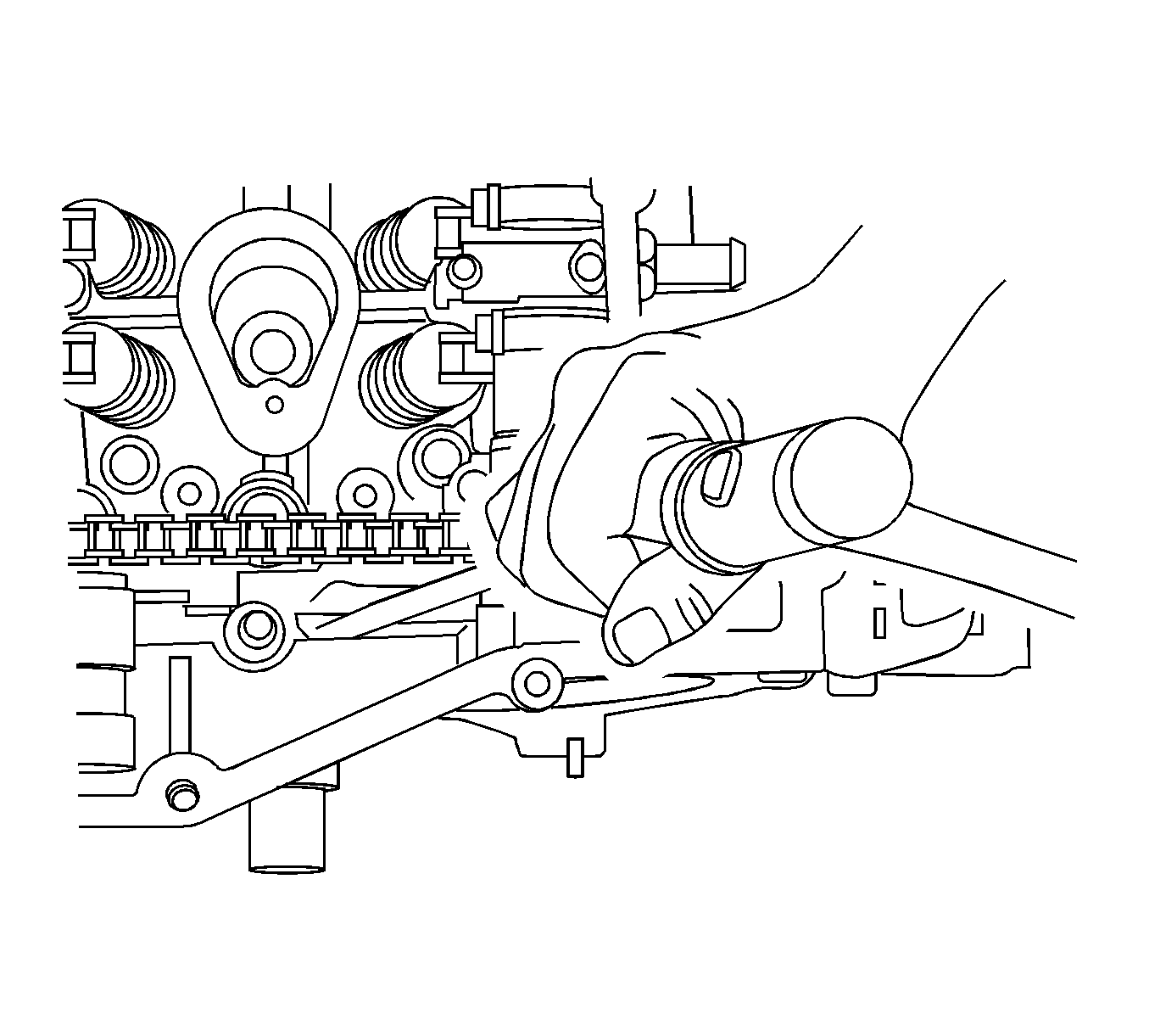
| 11.7. | Before performing one of the top dead center (TDC) procedures, break loose both the exhaust and intake camshaft sprocket bolts. Use a 25 mm (1 in) open end wrench on the camshaft hexes to hold the camshaft from turning.
DO NOT remove the bolts. |
| 11.8. | Perform one of the following methods for the service timing procedure. |
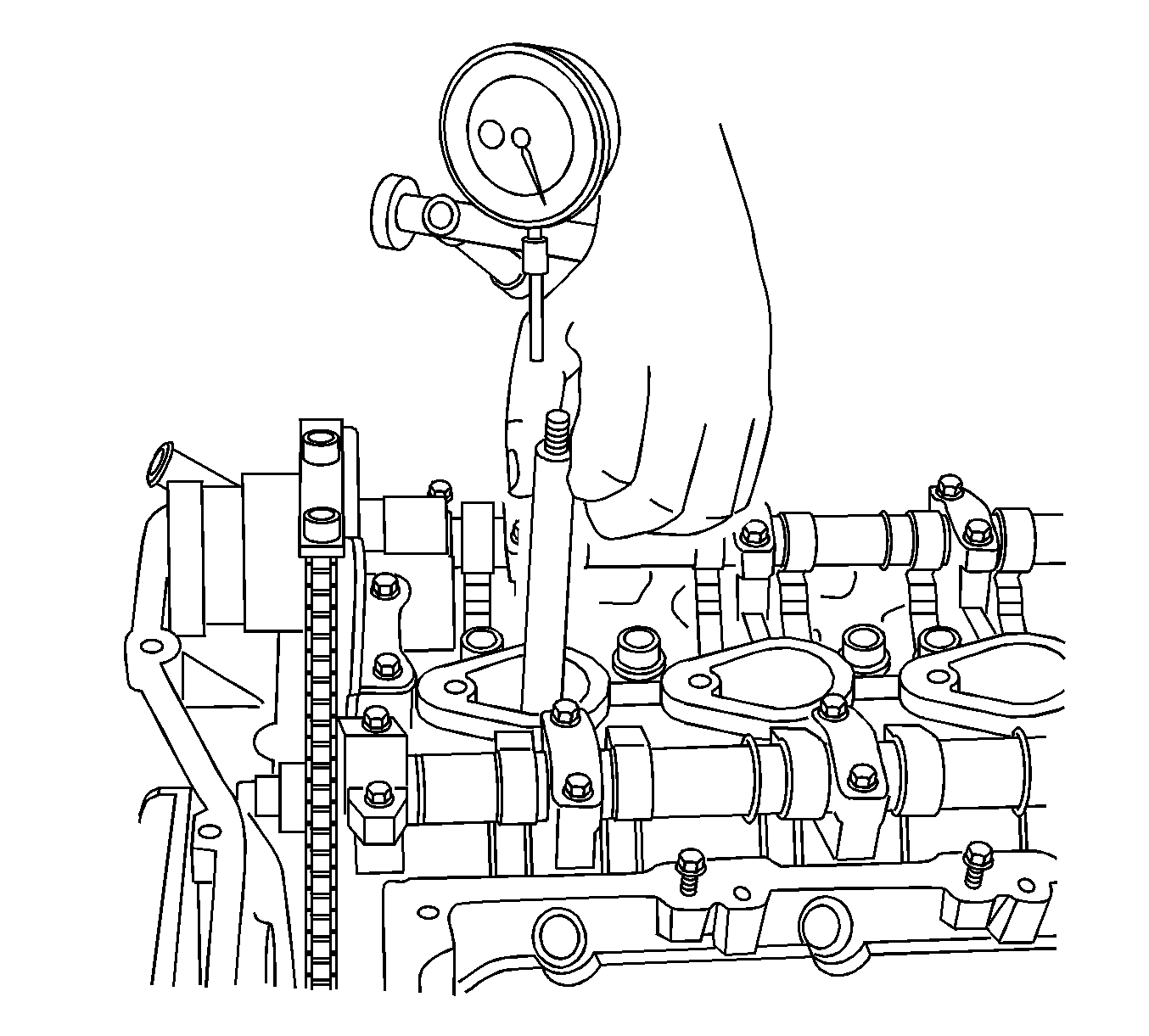
- First Method--Rotate the engine clockwise by hand to TDC on the compression stroke by using a piston TDC indicator tool and/or dial indicator in the number 1 cylinder.
- First Method (continued)--The TDC indicator tool graduation marks on the shaft should note top of the piston stroke.
- First Method (continued)--When the piston is at TDC, the flats at the rear of the camshafts will be facing up and level when using a straight edge across the camshaft flats.
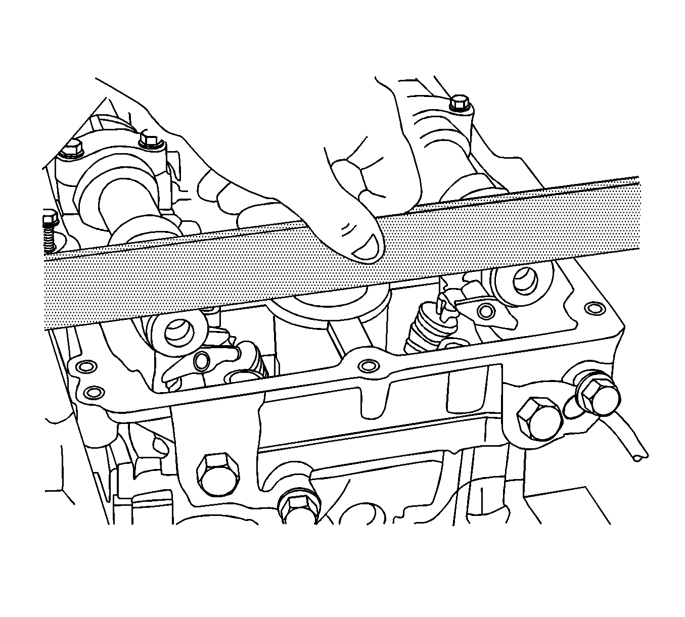
- Second Method--Rotate the crankshaft in the engine rotational direction clockwise until the number 1 piston is at TDC on the compression stroke. The word Delphi on the exhaust camshaft position actuator will be parallel
with the cylinder head to cam cover mating surface. When the piston is at TDC, the flats at the rear of the camshafts will be facing up and level when using a straight edge across the camshaft flats. A 0.005 inch feeler gage should not slide under the
straight edge (1).
- Once TDC is located for the number 1 cylinder using above methods, raise the vehicle and lock the flywheel with the
J 44226 .
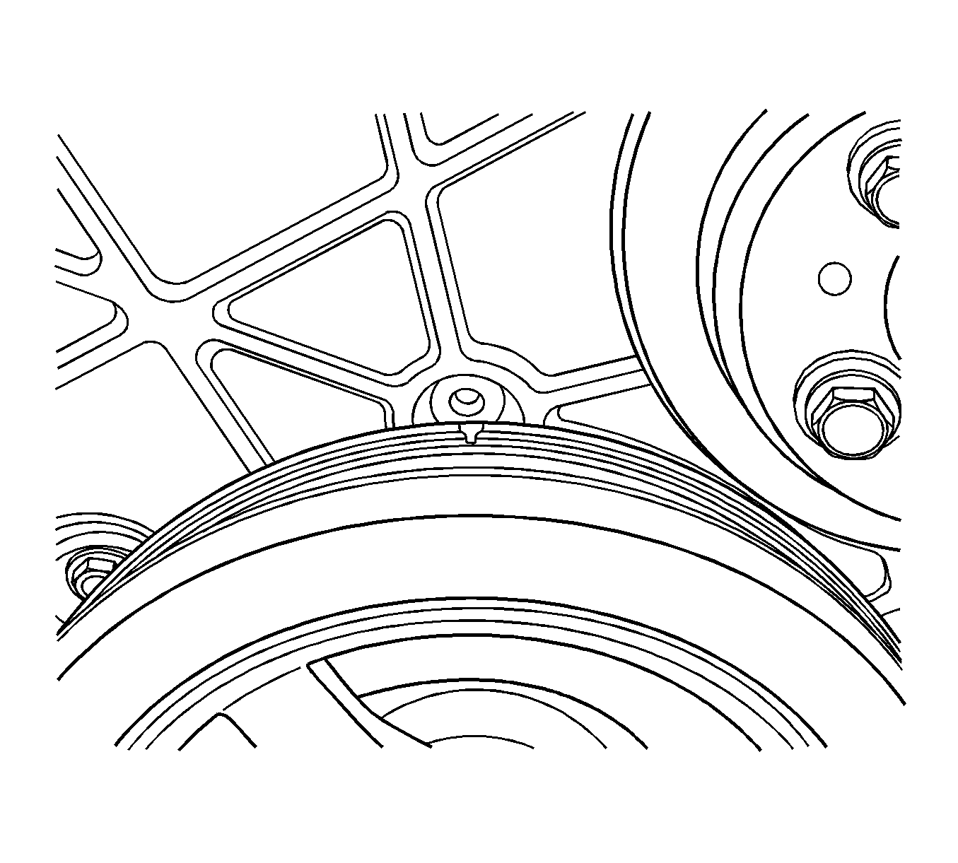
- Use a white paint pen or equivalent to place a reference mark on the harmonic balancer to the front cover for alignment purposes.
- Lower the vehicle.
Warning: The camshaft holding tools must be installed on the camshafts to prevent camshaft rotation. When performing service to the valve train and/or timing components, valve spring pressure can cause
the camshafts to rotate unexpectedly and can cause personal injury.
Note: If the timing is correct--TDC compression stroke number 1 cylinder--the camshaft flats will be in the up position.
- Install
J 44221 (1) to the back of the camshafts.
- Clean the timing chain and gears with brake cleaner or suitable solvent. Use a white paint pen or equivalent to place a reference mark on both timing gear sprockets and the timing chain to mark location prior to disassembly. It
is recommended that the paint marks be in the 12 o'clock position.
Caution: DO NOT use excessive force to seat the wedge tool. If excessive force is used, you may damage the timing chain tensioner
or break the front cover bolt requiring complete disassembly of the front engine.
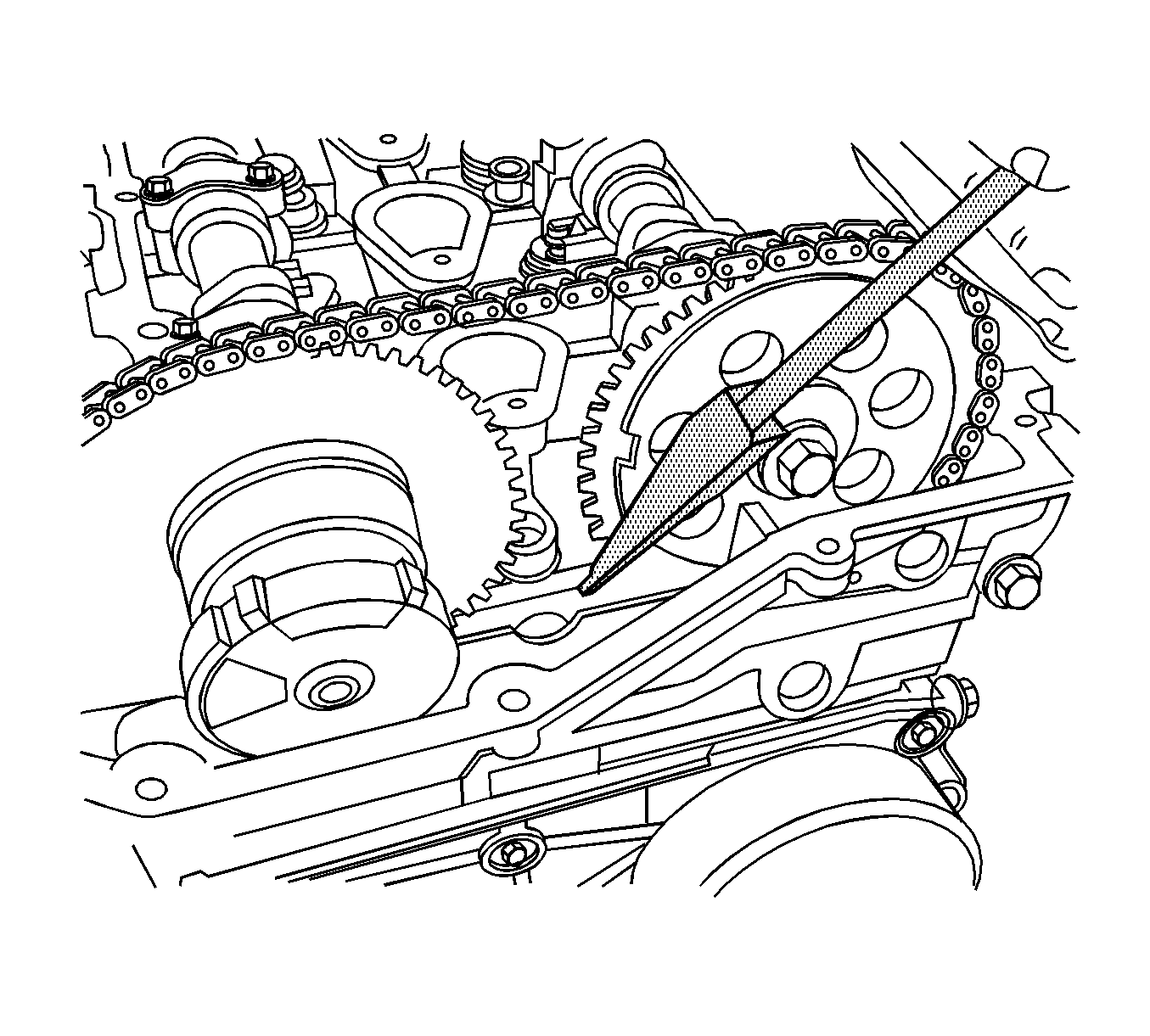
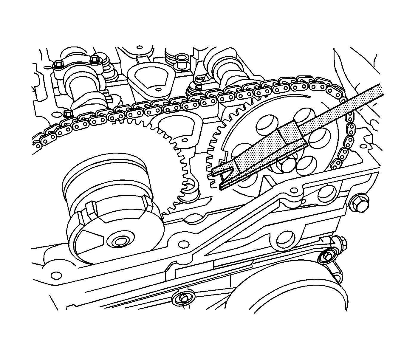
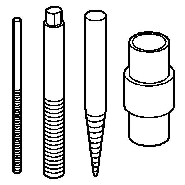
- Install
EN-48464 . It is important to install the tool with the proper orientation and to ensure that it is seated square against the timing chain and against the timing cover center
bolt.
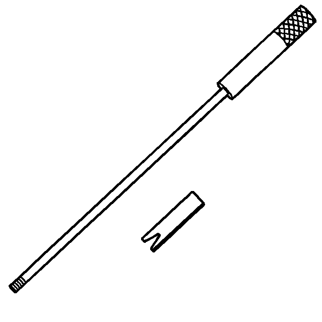
- The narrow ramp of the wedge tool needs to be placed so that it faces the timing chain. Front cover removed for illustration purposes.
- The wedge tool should be lightly seated using a couple of very light taps with a small plastic or brass hammer.
- Once the tool is correctly installed, unscrew the handle and remove the handle.
Note:
| • | Use a 25 mm (1 in) open end wrench on the camshaft hexes to hold the camshaft from turning. It is critical that the crankshaft does not move and is held at TDC when the intake and exhaust camshaft sprocket bolts are removed. |
| • | If the crankshaft is not held in place, the wedge tool could be dislodged. If the crankshaft moves, or if the tool is not seated properly allowing the timing chain tensioner to extend, the repair will have to be completed by removing the front cover
to release the timing chain tensioner. |
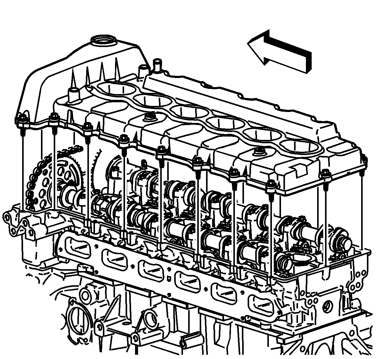
- Remove both upper cylinder head access hole plugs from the front of the cylinder head.
- Remove the 1 long and 2 short cylinder head bolts next to the exhaust and intake timing chain tensioner shoes and discard the bolts.
- Remove both upper timing chain tensioner shoe bolts.
- Remove the exhaust and the intake camshaft sprocket bolts. Discard the bolts.
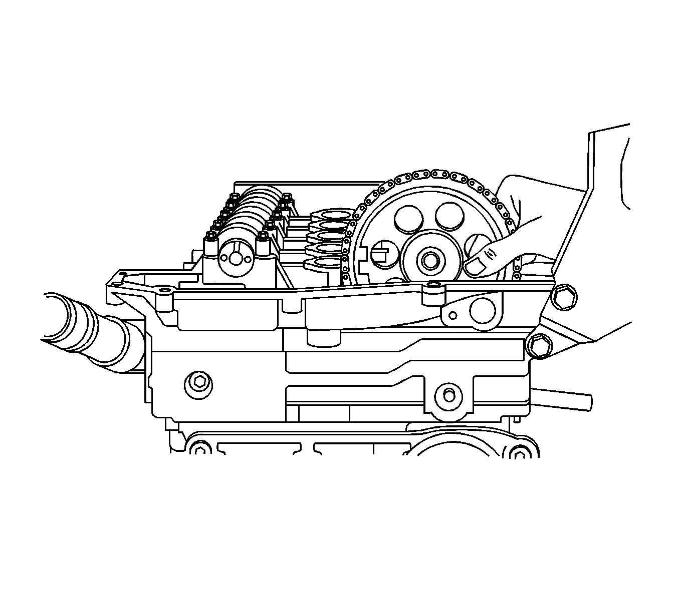
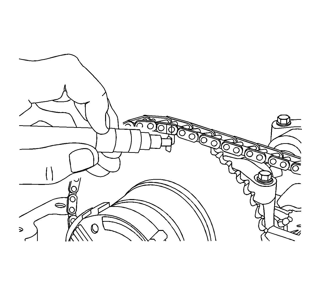
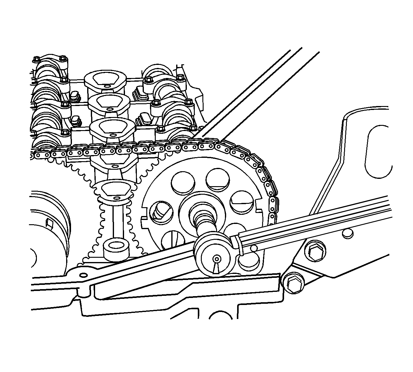
- Carefully remove the exhaust and intake camshaft sprockets with the timing chain from the exhaust and intake camshafts. The illustration shows the exhaust camshaft sprocket already removed.
- Remove the sprockets from the chain, tie a piece of mechanics wire on the timing chain and let it drop.
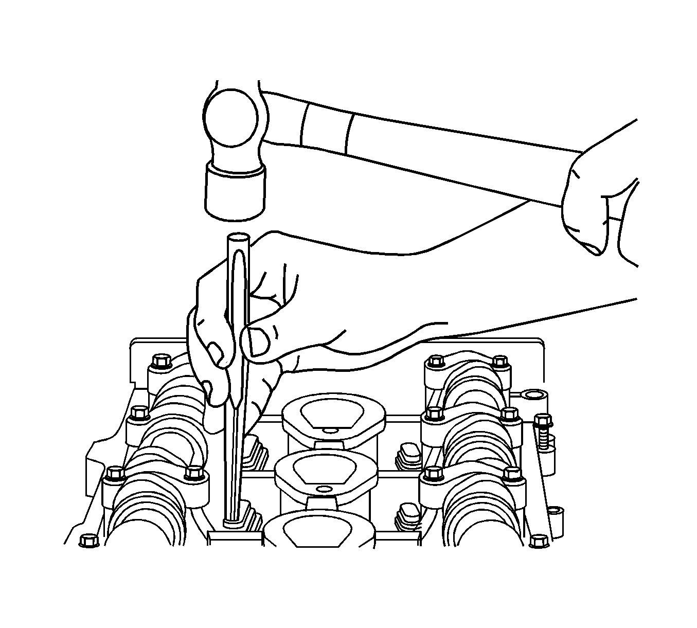
- Before removing the cylinder head bolts, use a drift punch and hammer to shock the bolts. This will ensure that the cylinder head bolts will not strip out the threads in the engine block or break. If a bolt breaks during engine
disassembly,
EN-47702 is available to assist in the removal of the remaining bolt segment.
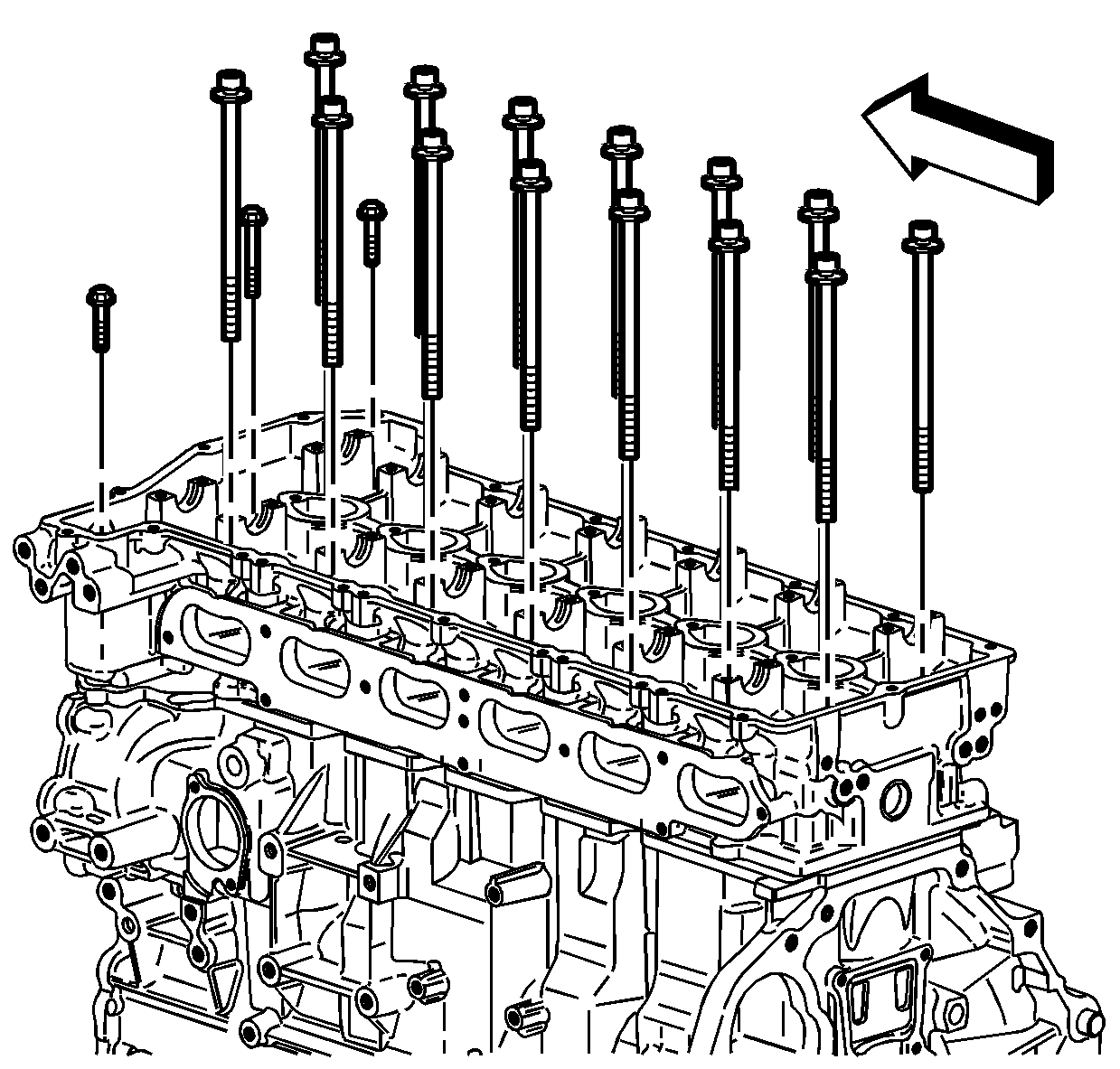
- Remove the cylinder head bolts. Discard the bolts.
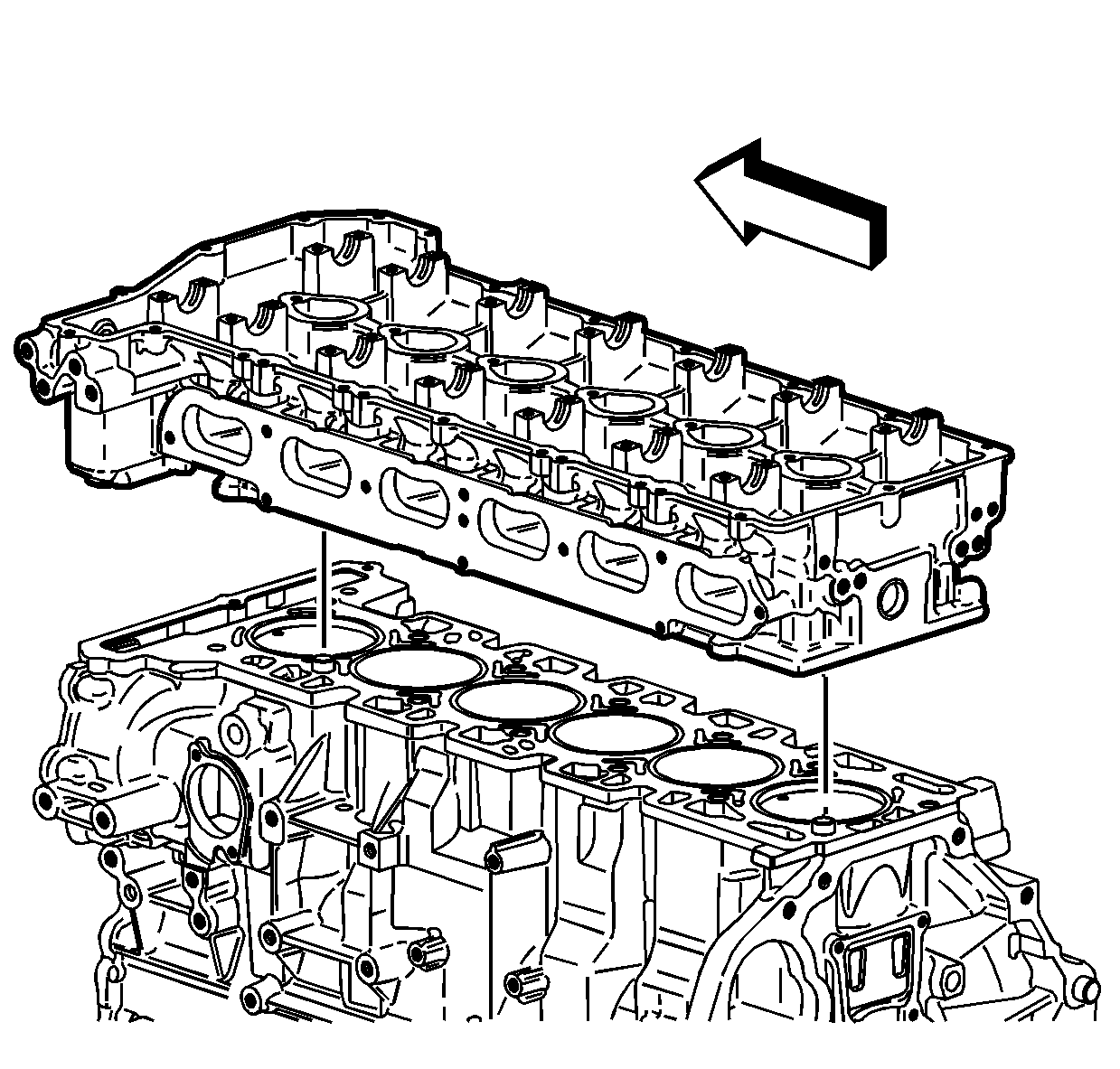
- Remove the cylinder head.
- Place the cylinder head on a flat, clean surface with the combustion chambers face up, in order to prevent damage to the deck face.
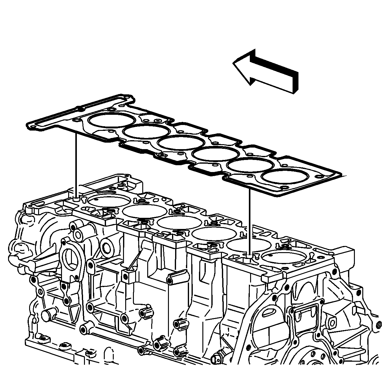
- Remove the cylinder head gasket.
Discard the gasket.
- Remove all remaining gasket material from the engine block.
- Inspect the cylinder head gasket mating surface on the engine block.
- Clean and inspect the cylinder head. Refer to
Cylinder Head Cleaning and Inspection.
- Disassemble the cylinder head if necessary. Refer to
Cylinder Head Disassemble.
- Assemble the cylinder head if necessary. Refer to
Cylinder Head Assemble.
- Install the dowel pins, cylinder head locator, if necessary.
- Position a NEW cylinder head gasket to the engine block.
Note: Ensure all wires, components, etc. are out of the way when installing the cylinder head.
- Install the cylinder head.
Caution: This component uses torque-to-yield bolts. When servicing this component do not reuse the bolts, New torque-to-yield bolts must be installed. Reusing used torque-to-yield bolts will not provide
proper bolt torque and clamp load. Failure to install NEW torque-to-yield bolts may lead to engine damage.
- Install NEW cylinder head bolts.
Caution: Refer to Fastener Caution in the Preface section.
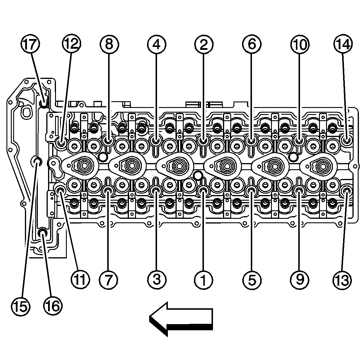
- Tighten the NEW cylinder head bolts in the following sequence:
| 6.1. | Tighten the cylinder head bolts (1-14) in sequence to
30 N·m (22 lb ft). |
Use the
J 45059 to rotate the cylinder head bolts (1-14)
in sequence an additional 155 degrees.
| 6.2. | Tighten the 2 short end bolts to
7 N·m (62 lb in). |
Use the
J 45059 to rotate the short cylinder head end bolts an additional 60 degrees.
| 6.3. | Tighten the 1 long end bolt to
7 N·m (62 lb in). |
Use the
J 45059 to rotate the long cylinder head end bolt an additional 120 degrees.
Warning: The camshaft holding tools must be installed on the camshafts to prevent camshaft rotation. When performing service to the valve train and/or timing components, valve spring pressure can cause
the camshafts to rotate unexpectedly and can cause personal injury.
Note: Before installing the camshafts, refer to
Camshafts Cleaning and Inspection.
- Install the camshafts with the flats up using
J 44221 (1). Refer to
Camshaft Installation.
Caution: Tension must be always kept on the intake side of the timing chain to properly keep the engine in time. If the chain is loose the timing will be off, which may cause internal engine damage or
set DTC P0017.
Caution: The exhaust camshaft actuator must be fully advanced during installation. Engine damage may occur if the camshaft actuator is not fully advanced.
- Ensure that the camshaft position actuator is in the fully advanced position. Refer to
Camshaft Position Actuator Diagnosis.
Note: To aid in aligning the actuator to the camshaft, use a 25 mm (1 in) open end wrench on the hex of the camshaft to rotate. This will ensure the alignment pin is properly engaged with the camshaft and hand tighten the
new exhaust camshaft sprocket bolt.
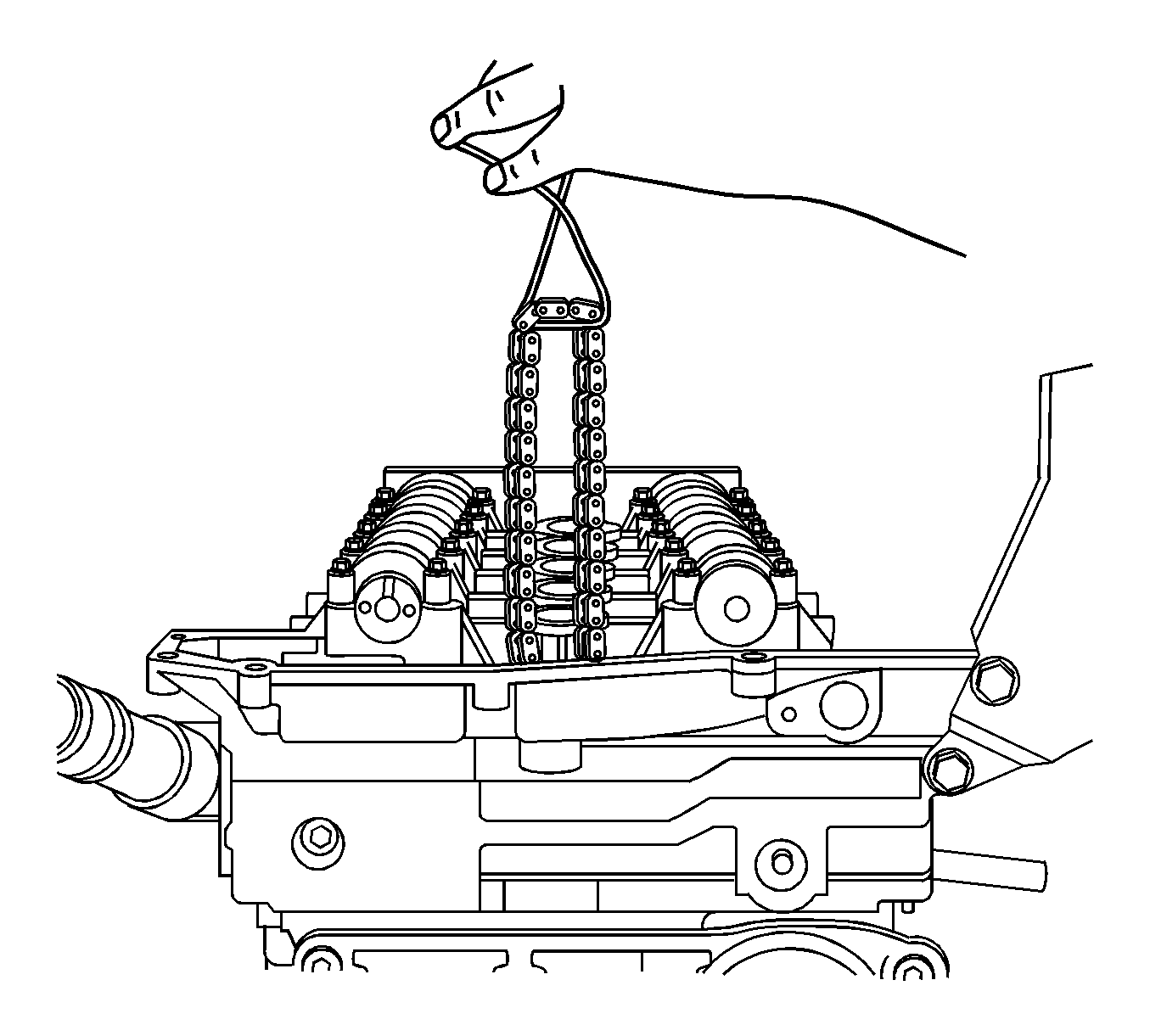
- Install the exhaust camshaft actuator/sprocket and chain onto the exhaust camshaft. Use the paint marks as an alignment guide.
Note: To aid in aligning the intake sprocket to the camshaft, use a 25 mm (1 in) open end wrench on the hex of the camshaft to rotate. This will ensure the alignment pin is properly engaged with the camshaft and hand tighten
the new intake camshaft sprocket bolt.
- Install the intake camshaft sprocket and chain onto the intake camshaft. Use paint marks as alignment guide.
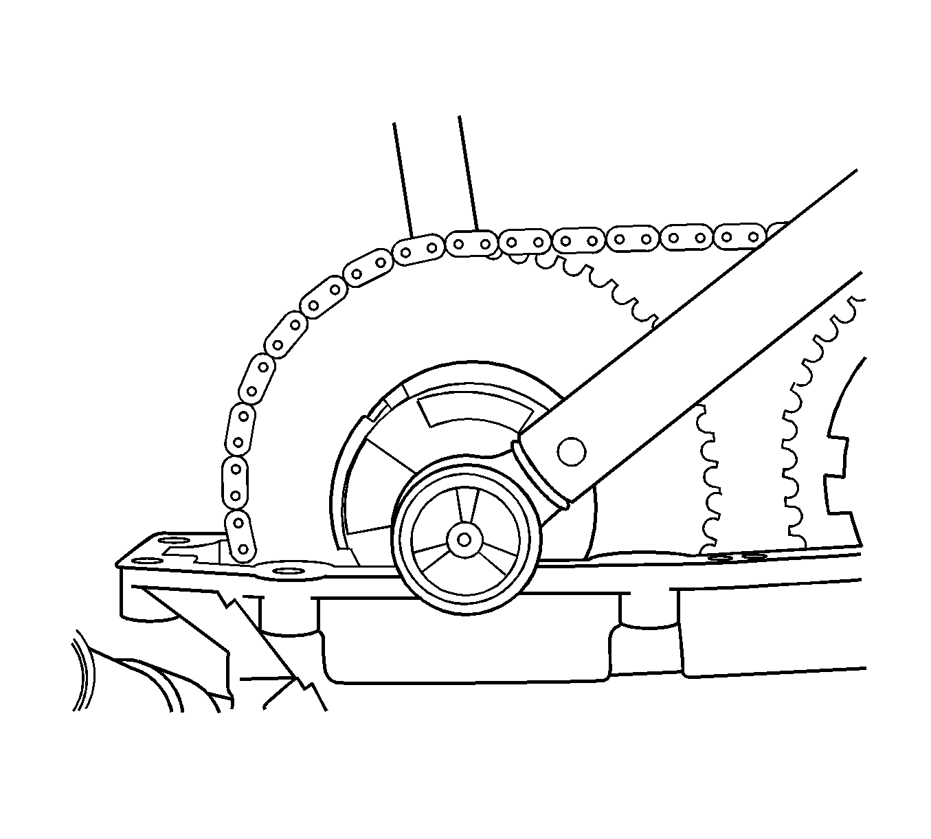
- Position the timing chain tensioner shoe to the engine.
- Install the timing chain tensioner shoe bolt and tighten to
25 N·m (18 lb ft).
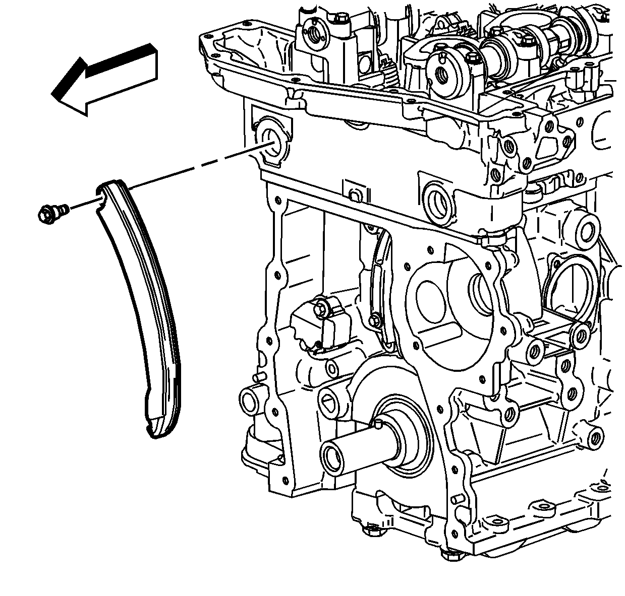
- Position the lower timing chain guide to the engine.
- Install the lower timing chain guide bolts and tighten to
12 N·m (107 lb in).
- Install both upper timing chain tensioner shoe bolts and tighten to
25 N·m (18 lb ft).
- Install both upper cylinder head access hole plugs to the front of the cylinder head and tighten to
5 N·m (44 lb in).
- Tighten the new intake camshaft sprocket bolt. Using
J 45059 , tighten the intake camshaft sprocket bolt to
20 N·m (15 lb ft) plus
100 degrees.
- Tighten the new exhaust camshaft actuator sprocket bolt. Using
J 45059 , tighten the exhaust camshaft actuator sprocket bolt to
25 N·m (18 lb ft) plus 135 degrees.

- Lift the vehicle and remove the
J 44226 .
- Lower the vehicle.
- Remove the
J 44221 from the back of the camshafts.
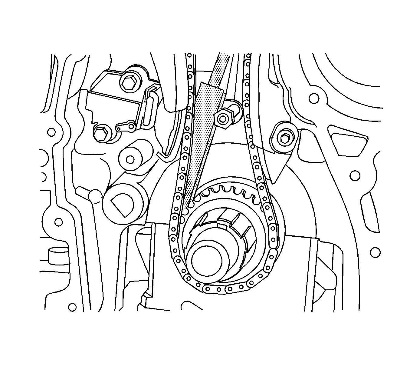
Caution: Ensure that the wedge tool is removed from engine prior to rotation. If the wedge tool is not removed, engine damage will result.
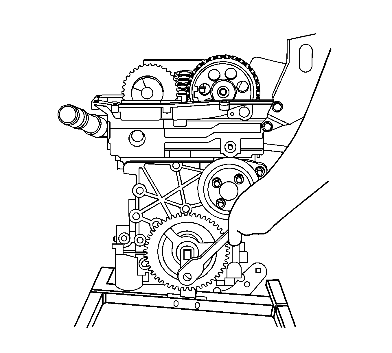
- Install the handle of
EN-48464 and remove the wedge portion of the tool from the engine.
Note: It is critical that the engine is at TDC and not a couple of degrees off. If in doubt, repeat this step.
- Rotate the engine clockwise by hand two complete revolutions to TDC number 1 on the compression stroke. Refer to First Method or Second Method for TDC. If you go past TDC, rotate the engine back approximately 45 degrees before TDC and then
rotate clockwise up to TDC to ensure that the timing chain is tight (no slack) between the crank sprocket and the timing gears.
Note: DO NOT use the
J 44221 (1) , installed to the back of the camshafts, as a method to verify timing.
- Both intake and exhaust camshaft flats should be facing up and flat and level with the cylinder head. If
J 44221 is used to verify cam timing, you could be off approximately one tooth and cause DTC P0017 to
set. If a worn or new
J 44221 is used to verify timing, the timing will be off.
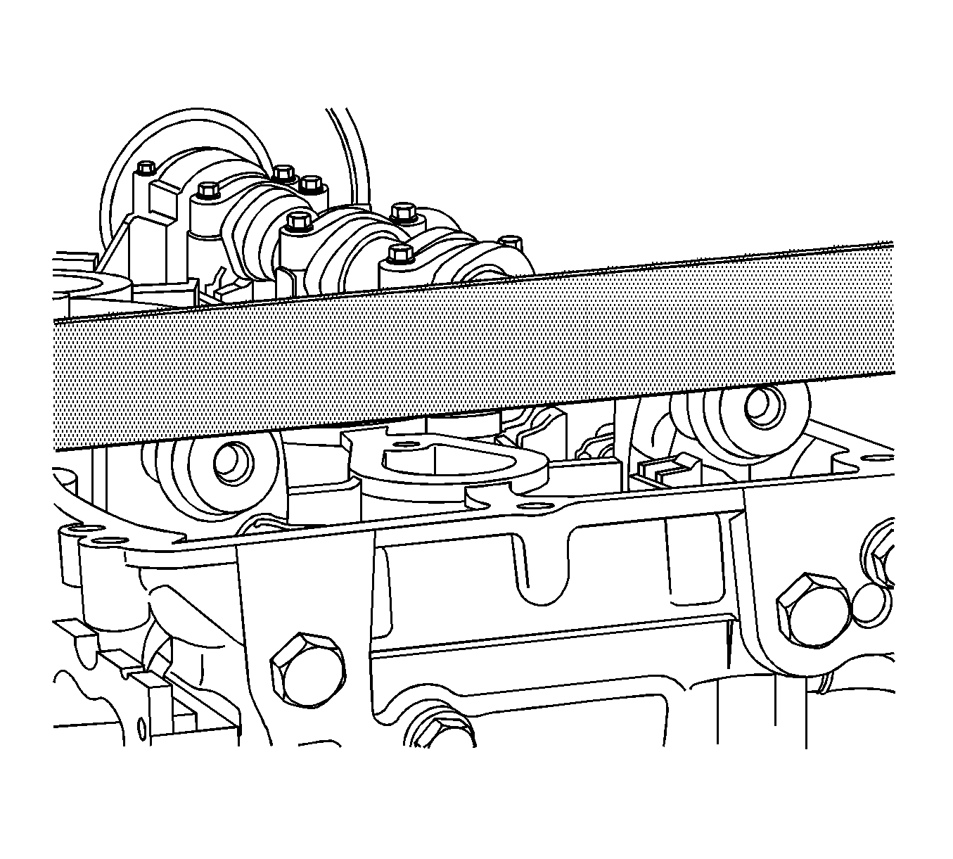
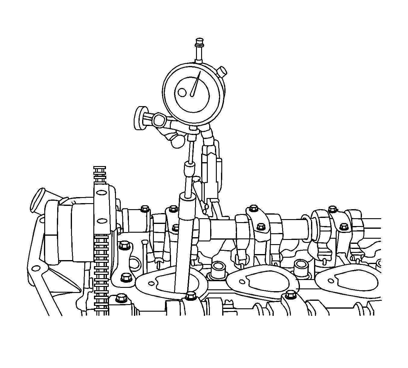
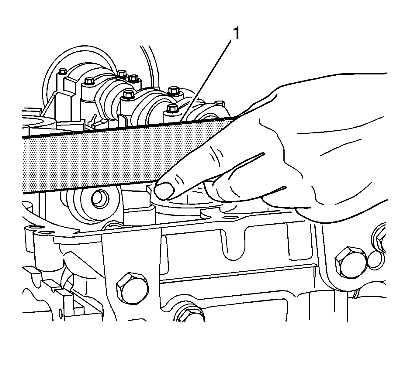
- To verify timing, set a straight edge across the flats of the camshafts.
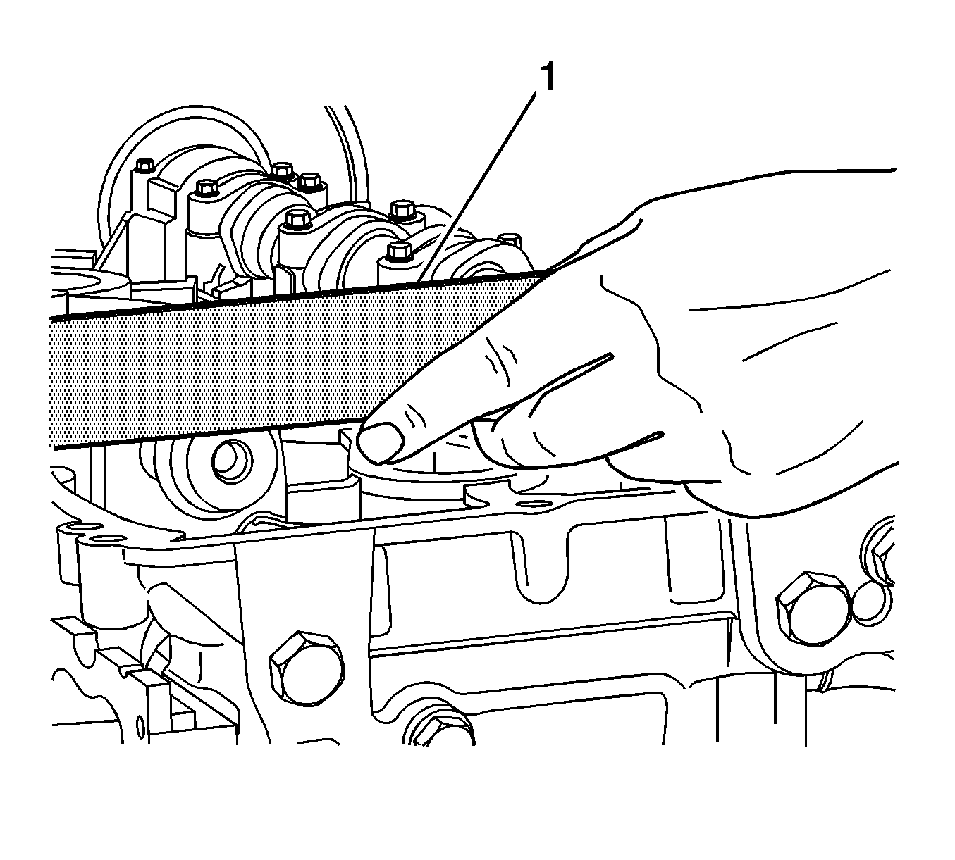
- A 0.005 inch feeler gage should not be able to slip under the straight edge (1). If the feeler gage slips under one or both camshaft flats, then the timing is off. Repeat step 20 and recheck. If the camshaft
flats are still not flat, the camshaft timing will have to be reset. This may require removal and reinstallation of one or both camshaft sprockets.
- Install the 1 long and 2 short cylinder head bolts next to the exhaust and intake timing chain tensioner shoes and tighten the bolts.
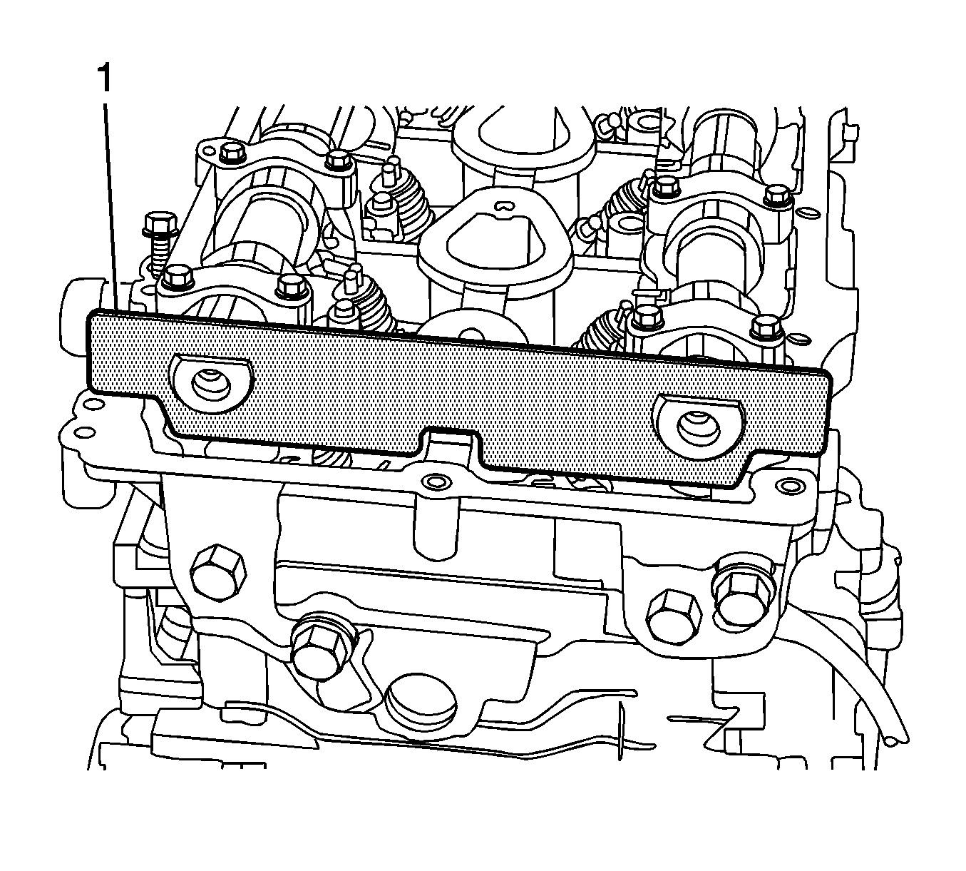
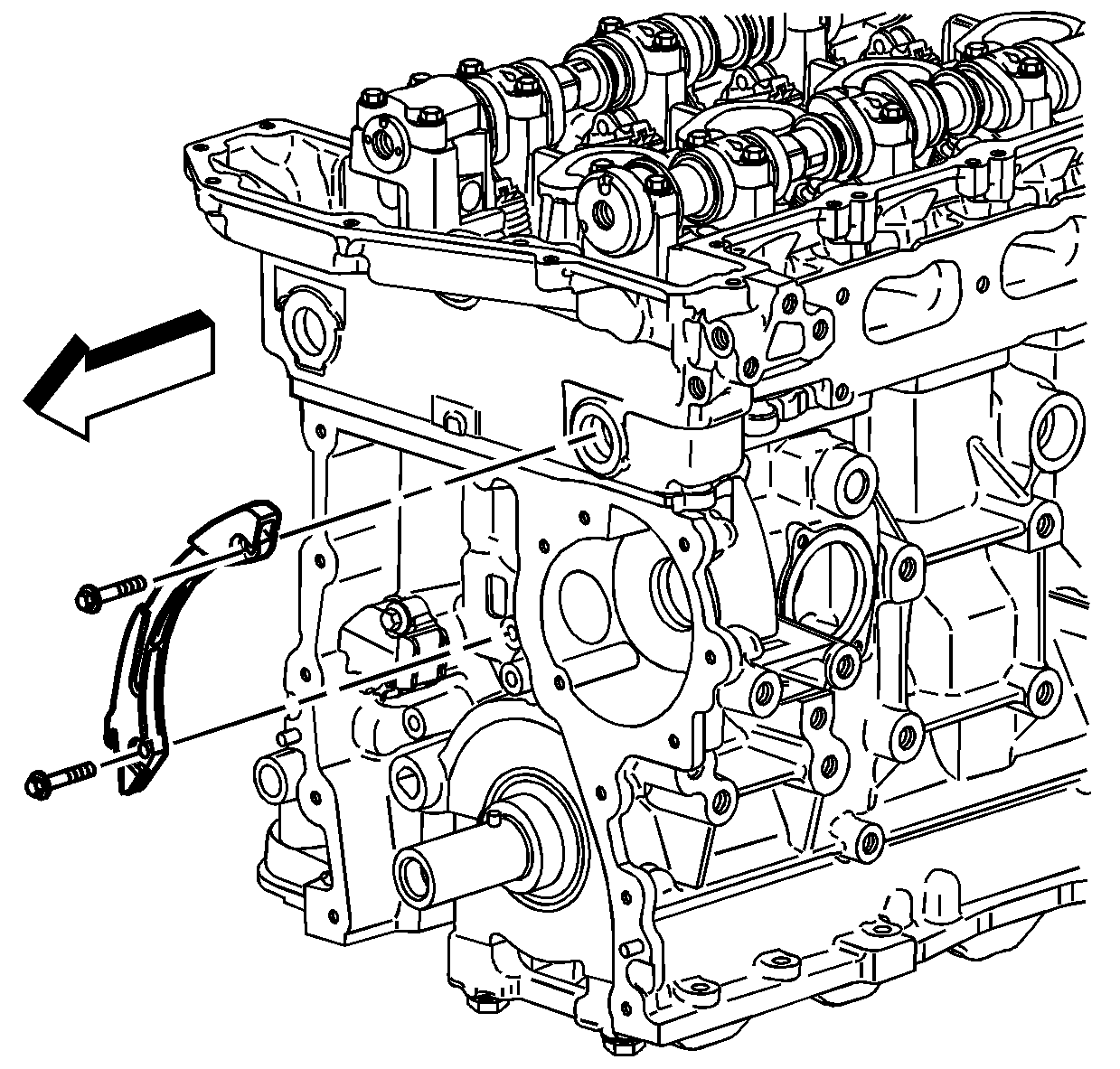
- Position the upper timing chain guide to the cylinder head. Apply threadlocker GM P/N 89021297 (Canadian P/N 10953488) to the upper timing chain guide bolt threads.
- Install the upper timing chain guide bolts and tighten to
10 N·m (89 lb in).
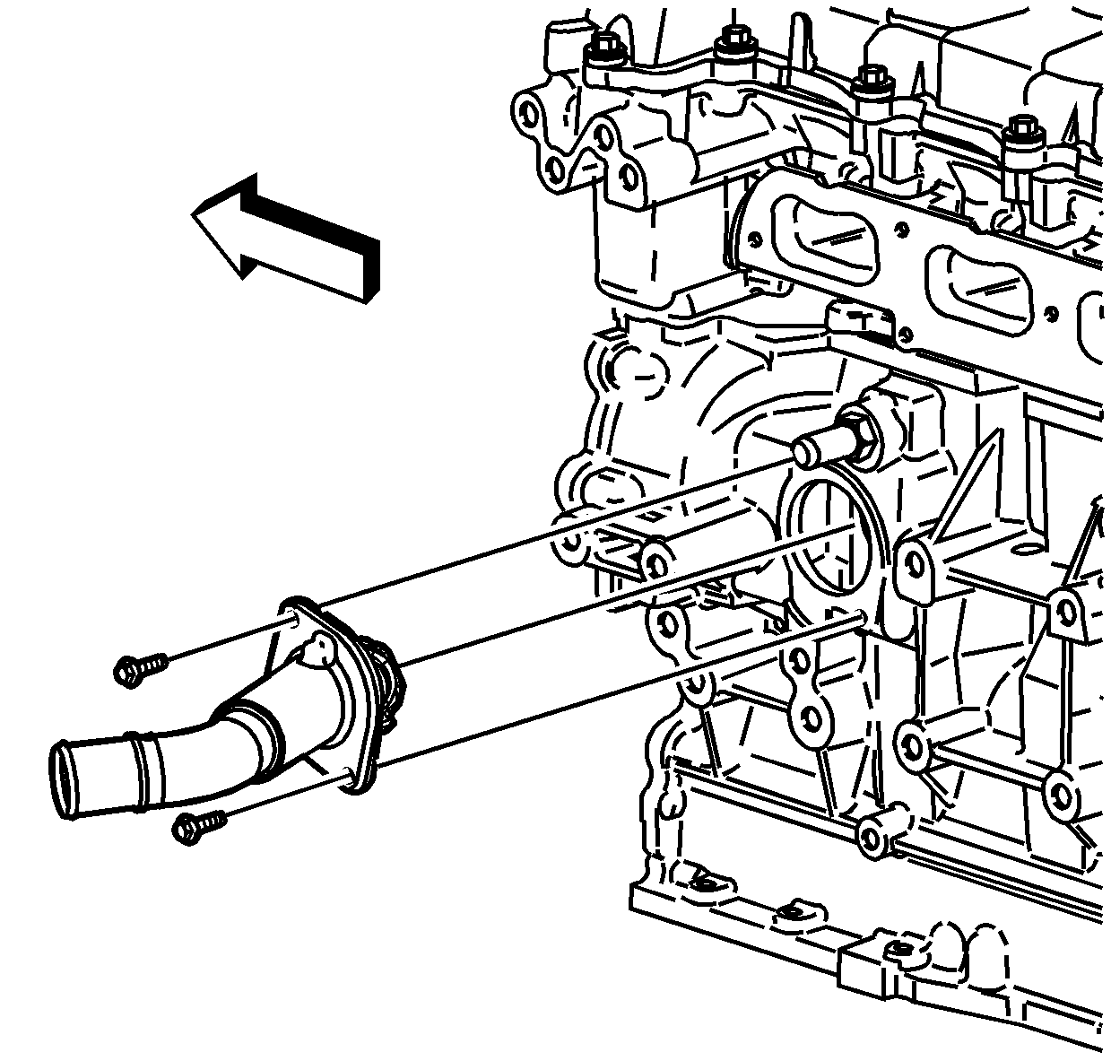
- Install the radiator inlet hose and clamp to the cylinder head. Refer to
Radiator Inlet Hose Replacement.
- Clean and inspect the camshaft cover. Refer to
Camshaft Cover Cleaning and Inspection.
- Install a NEW camshaft cover seal and NEW ignition control module seals to the cam cover. Position the camshaft cover to the cylinder head.
- Install the camshaft cover bolts and tighten to
10 N·m (89 lb in).
- Check the gap on all of the spark plugs. The gap should be 1.08 mm (0.042 in). Tighten all of the spark plugs to
18 N·m (13 lb ft).
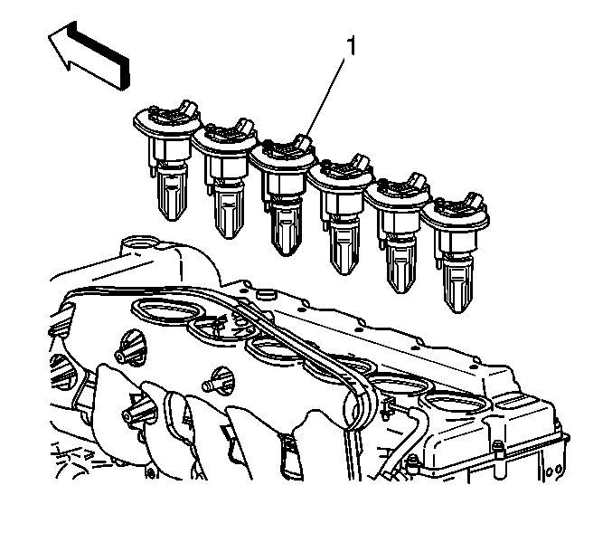
- Install the ignition coils (1) into the camshaft cover.
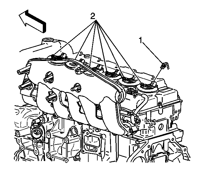
- Install the ignition coil bolts (2) and tighten to
10 N·m (89 lb in).
- Reposition the exhaust manifold to cylinder head and install the exhaust manifold bolts to the cylinder head. Refer to
Exhaust Manifold Replacement.
- If equipped, install a NEW AIR injection gasket, then the cover and pipe studs to the cylinder head and tighten to 25 N·m (18 lb ft).
- Install the exhaust manifold heat shield to the exhaust manifold.
- Apply anti-seize GM P/N 12371386 (Canadian P/N 89021945) to the exhaust manifold heat shield nuts.
- Install the exhaust manifold heat shield nuts and tighten to
10 N·m (89 lb in).
- Install the intake manifold to the cylinder head. Refer to
Intake Manifold Replacement.
Four-wheel drive--Raise the vehicle and install the blind intake manifold bolts from the left front wheelhouse access.
Two-wheel drive--The bolts are accessible from the top of the engine.
- Reposition the engine wiring harness bracket to the engine and harnesses. Install the engine wiring harness bracket bolts and tighten to
10 N·m (89 lb in).
- Install the left front wheelhouse panel and the left wheel and tire. Refer to
Wheelhouse Panel Replacement.
- Drain the engine oil again.
- If removed, install the radiator outlet hose. Refer to
Radiator Outlet Hose Replacement.
- Install the cross-vehicle wiring harness connectors to the following components:
| • | Harness clamps at power steering pump |
| • | Wiring harness fastener at right front inner fender |
| • | Exhaust camshaft actuator |
| • | AIR valve and connectors |
- Install the PCV pipes to the intake manifold. Refer to
Positive Crankcase Ventilation Hose/Pipe/Tube Replacement.
- Reposition the Fuel/EVAP lines to the intake manifold retainer. Refer to
Evaporative Emission Hoses/Pipes Replacement - Engine/Chassis.
- Install the following components:
- Install the air cleaner element and resonator. Refer to
Air Cleaner Element Replacement and
Air Cleaner Outlet Resonator Replacement.
- Install NEW engine oil. Refer to
Engine Mechanical Specifications.
- Install NEW coolant. Refer to
Cooling System Draining and Filling.
- Install a scan tool and start the engine.
