Removal Procedure
- Disable the inflatable restraint steering wheel module. Refer to Disabling the SIR System in SIR.
- Remove the steering wheel. Refer to Steering Wheel Replacement .
- Remove the tilt lever. Refer to Tilt Lever Replacement - On Vehicle .
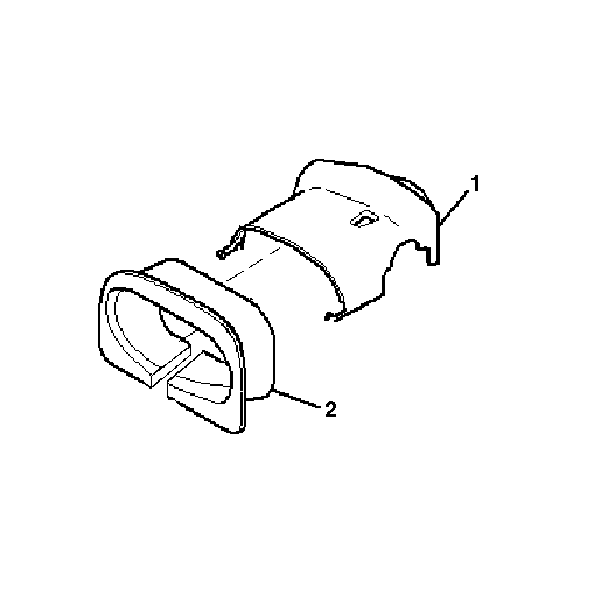
- Disengage the closeout trim cover (2) from the upper trim cover (1) in the following manner:
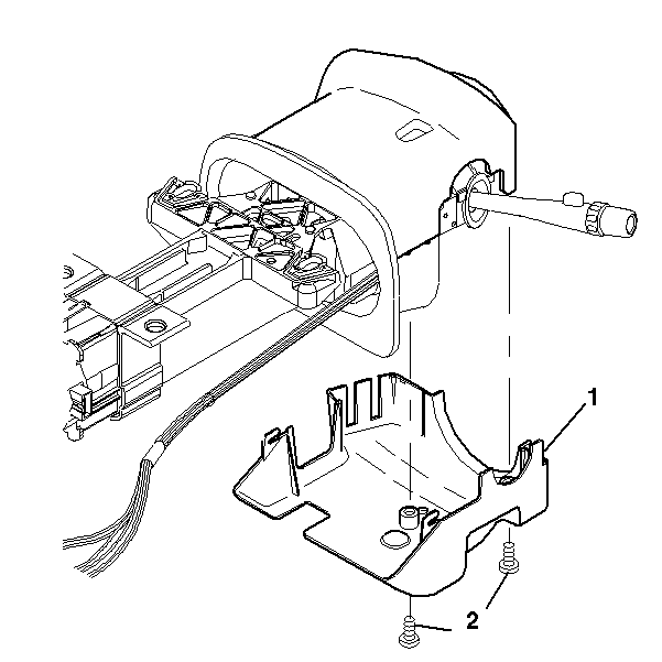
- If necessary, remove the 2 pan head tapping screws (2) from the lower trim cover (1). Remove the lower trim cover (1).
- If no screws are present in the lower trim cover, proceed to the next step.
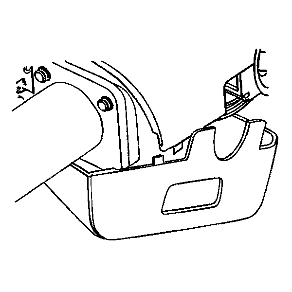
- Gently unsnap the lower trim cover from the upper trim cover.
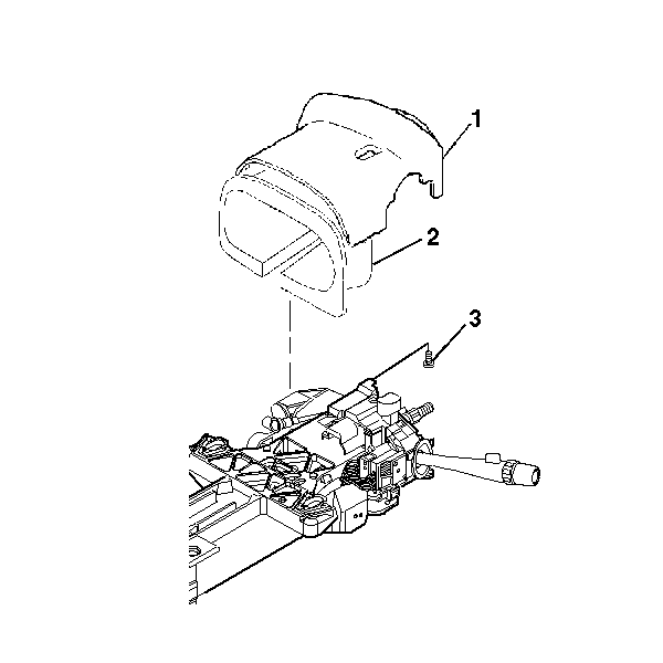
- If necessary, remove 1 TORX® head screw (3) from the upper trim cover (1) and the closeout trim cover (2) for removal.
- If no screw is present, remove the upper trim cover (1) with the closeout trim cover (2).

Caution: This vehicle is equipped with a Supplemental Inflatable Restraint (SIR) System. Failure to follow the correct procedure could cause the following conditions:
• Air bag deployment • Personal injury • Unnecessary SIR system repairs • Refer to SIR Component Views in order to determine if you are performing service on or near the SIR components or the SIR wiring. • If you are performing service on or near the SIR components or the SIR wiring, disable the SIR system. Refer to Disabling the SIR System.
Important: The closeout trim cover must be removed in the exact order listed below in order not to damage the snaps on the upper trim cover.
| 4.1. | Stand in front of the column from the drivers point of view. |
| 4.2. | On the left side, gently pull downwards on the left side of the closeout trim cover to loosen 1 snap. Do not fully remove the closeout trim cover. |
| 4.3. | On the right side, gently pull downwards on the right side of the closeout trim cover to loosen 1 snap. Do not fully remove the closeout trim cover. |
| 4.4. | Starting from the left side of the trim covers, gently roll the closeout trim cover to the right to disengage the remaining 4 snaps. |

Important: You must inspect for 2 pan head tapping screws (2) in the lower trim cover (1) before removal.


Important: You must inspect for 1 TORX® head screw (3) in the upper trim cover (1) before removal.
Installation Procedure
- Install the upper trim cover (1) with the closeout trim cover (2) and secure by using 1 TORX® head screw (3).
- Install the lower trim cover (1).
- Connect the lower trim cover (1) to the closeout trim cover.
- Install 2 pan head tapping screws (2).
- Install the upper and lower trim covers onto the steering column.
- Gently snap the upper and lower trim covers together.
- If necessary, install the closeout trim cover (2) onto the upper trim cover (1).
- Install the tilt lever. Refer to Tilt Lever Replacement - On Vehicle .
- Install the steering wheel. Refer to Steering Wheel Replacement .
- Enable the inflatable restraint steering wheel module. Refer to Enabling the SIR System in SIR.

Notice: Use the correct fastener in the correct location. Replacement fasteners must be the correct part number for that application. Fasteners requiring replacement or fasteners requiring the use of thread locking compound or sealant are identified in the service procedure. Do not use paints, lubricants, or corrosion inhibitors on fasteners or fastener joint surfaces unless specified. These coatings affect fastener torque and joint clamping force and may damage the fastener. Use the correct tightening sequence and specifications when installing fasteners in order to avoid damage to parts and systems.
Important: If the snap on/off feature on the trim covers was damaged during the removal procedure, you must use screws for the installation procedure. If screws were present in the trim covers before the removal procedure, you must use the screws during the installation procedure.
If there was not any damage done to the trim covers during the removal procedure and no screws were present, proceed to step 6.Tighten
Tighten the screw to 1.0 N·m (9 lb in).

Tighten
Tighten the screws to 3.5 N·m (31 lb in).


