Tools Required
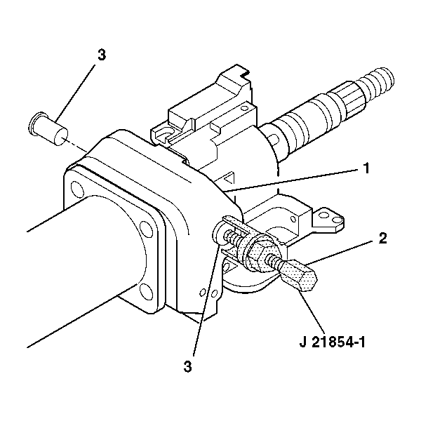
J 21854-01 Pivot Pin Remover
Removal Procedure
- Disable the inflatable restraint steering wheel module. Refer to Disabling the SIR System in SIR.
- Remove the steering column from the vehicle. Refer to Steering Column Replacement .
- Remove the ignition lock cylinder case assembly. Refer to Ignition Lock Cylinder Case Replacement .
- Remove the turn signal and multifunction switch assembly. Refer to Multifunction, Turn Signal, and Hazard Switch Replacement .
- Remove the turn signal switch housing. Refer to Multifunction Turn Signal Switch Housing Replacement .
- Remove the tilt spring. Refer to Steering Column Tilt Spring Replacement .
- Remove the 2 pivot pins (3) from the steering column tilt head assembly (1) using J 21854-01 .
- Install the tilt lever into the steering column tilt head assembly (1).
- Pull back on the tilt lever and at the same time pull the steering column tilt head assembly (1) down and away from the steering column.
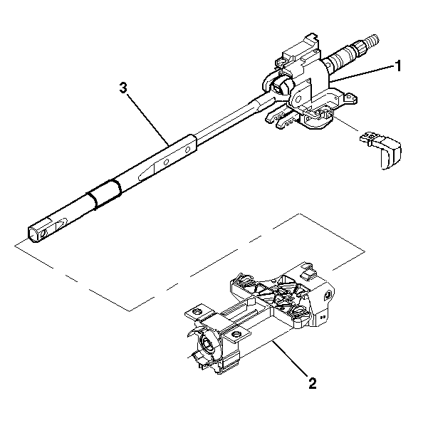
- Remove the steering column tilt head assembly (1) with the steering shaft assembly (3) from the steering column jacket assembly (2).
- Remove the tilt lever.
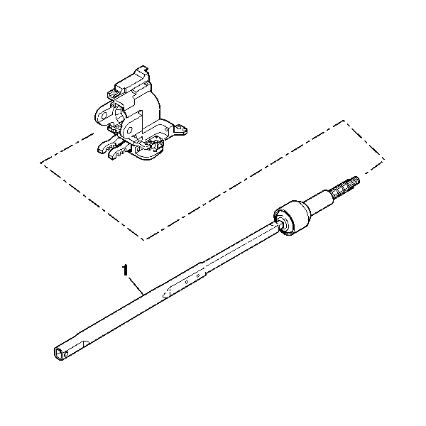
- Remove the steering shaft (1) from the steering column tilt head assembly.

Caution: This vehicle is equipped with a Supplemental Inflatable Restraint (SIR) System. Failure to follow the correct procedure could cause the following conditions:
• Air bag deployment • Personal injury • Unnecessary SIR system repairs • Refer to SIR Component Views in order to determine if you are performing service on or near the SIR components or the SIR wiring. • If you are performing service on or near the SIR components or the SIR wiring, disable the SIR system. Refer to Disabling the SIR System.


Installation Procedure
- Install the steering shaft (1) into the steering column tilt head assembly.
- Install the steering shaft (3) into the steering column tilt head assembly (1).
- Align the steering column tilt head assembly with the pivot pin holes on the steering column jacket assembly.
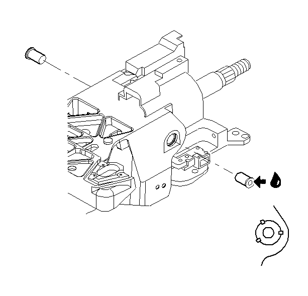
- Lubricate the pivot pins with GM specified lubricant.
- Stake the pins in 3 places.
- Install the tilt spring assembly only. Refer to Steering Column Tilt Spring Replacement .
- Install the turn signal switch housing only. Refer to Multifunction Turn Signal Switch Housing Replacement .
- Install the turn signal and multifunction switch assembly only. Refer to Multifunction, Turn Signal, and Hazard Switch Replacement .
- Install the ignition lock cylinder case assembly. Refer to Ignition Lock Cylinder Case Replacement .
- Install the steering column to the vehicle. Refer to Steering Column Replacement .
- Enable the inflatable restraint steering wheel module. Refer to Enabling the SIR System in SIR.


Install the tilt head assembly (1) and the steering shaft (3) into the steering column jacket assembly (2).
Important: The tilt head lock shoe teeth must be resting on the bar in the steering column jacket assembly.

Install the 2 pivot pins into the steering column support assembly.
