Tools Required
| • | J 23907 Slide Hammer with Bearing Adapter |
| • | J 26941 Bushing/Bearing Remover (3-4 inch) |
| • | J 36513 Gear and Bearing Separator Plate |
| • | J 44707 T Bar Push Puller |
| • | J 44737 Shift Rail Bearing Remover |
| • | J 44759 Adapter 3/8 NC to 5/8 NF |
| • | J 45358 Case Spreader |
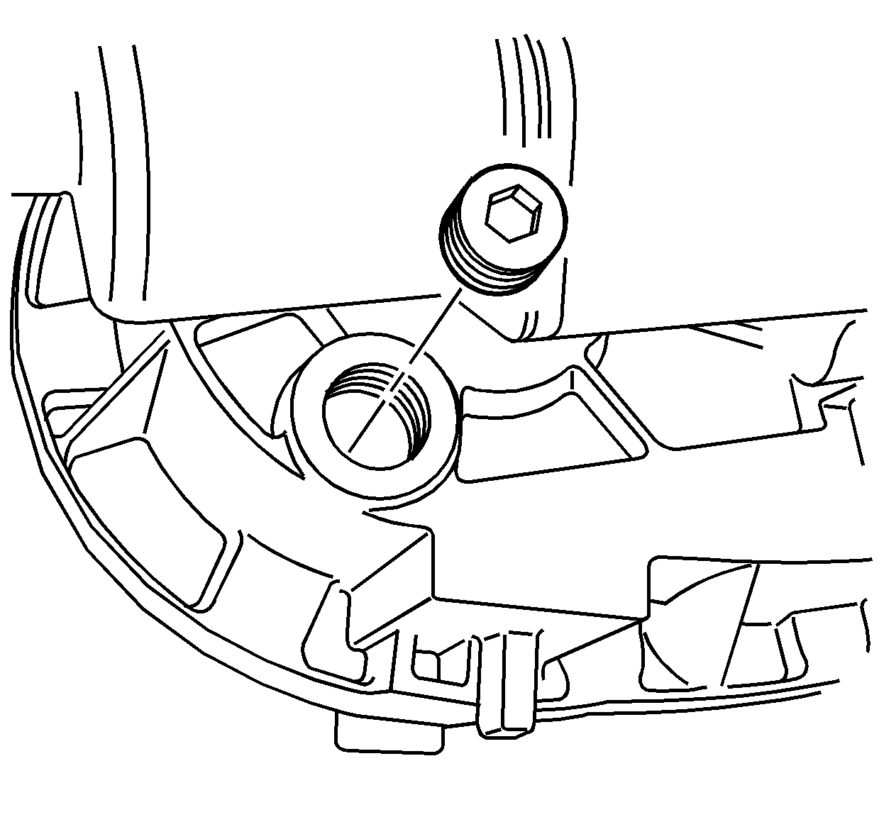
- Remove the drain plug.
- Tip the transfer case to remove any remaining transfer case fluid.
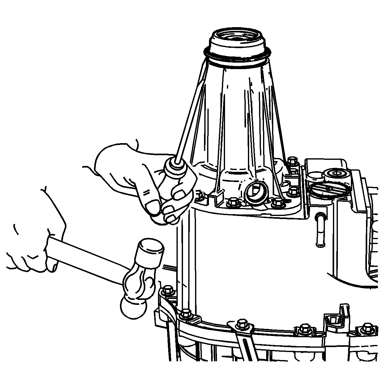
- Using a fine flat-bladed screwdriver and a mallet, loosen the front input shaft seal.
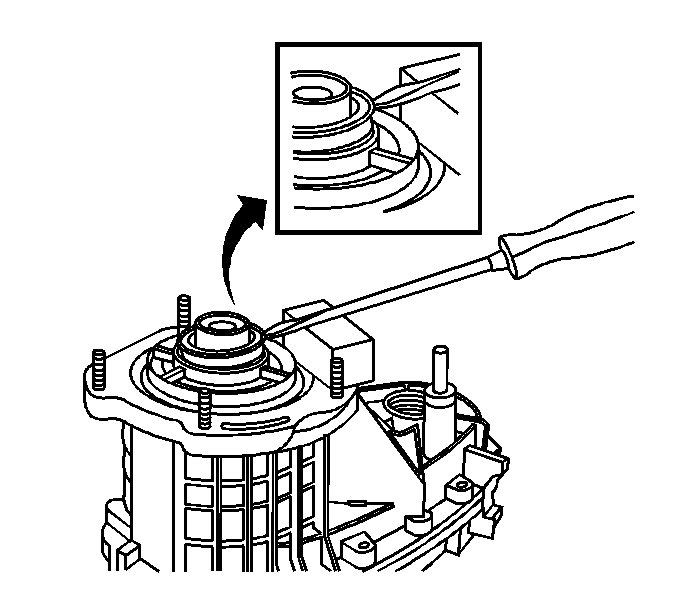
- Using a small block of wood and a large flat-bladed screwdriver, remove the front input shaft seal from the transfer case.
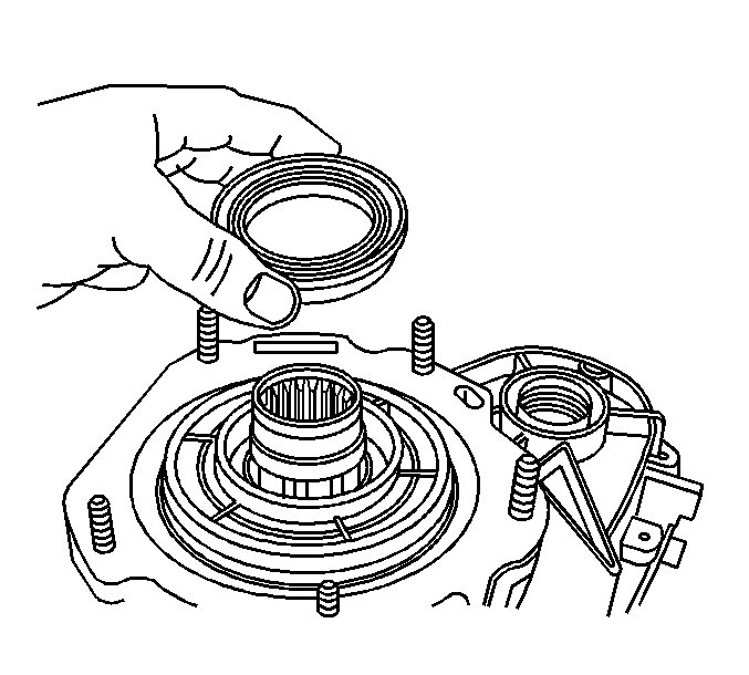
- Remove the front input shaft seal.
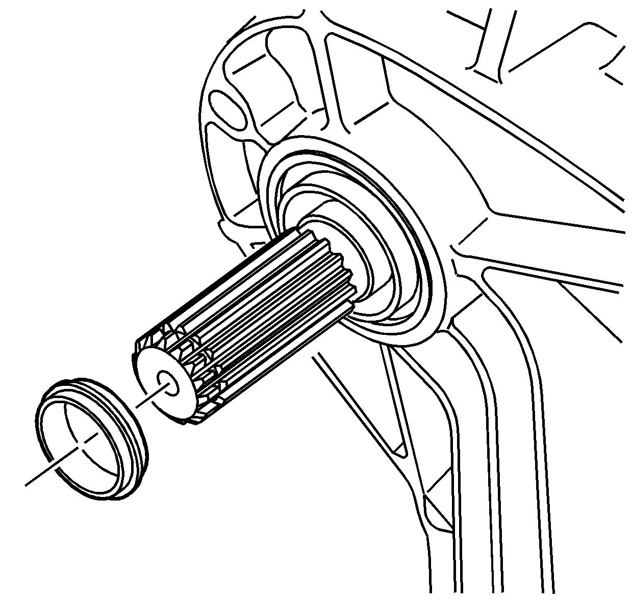
- Remove the dust seal from the front output shaft. The front output shaft oil seal does not require removal at this time.
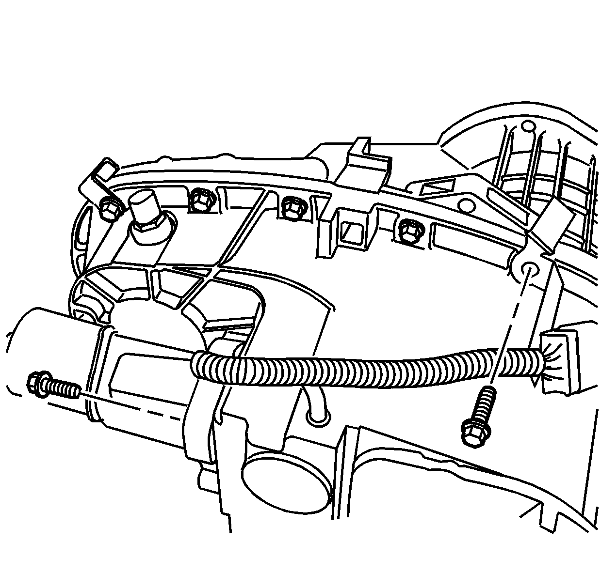
- Remove the transfer case bolt that is retaining the wiring harness bracket.
- Mark the location of the wiring harness bracket bolt.
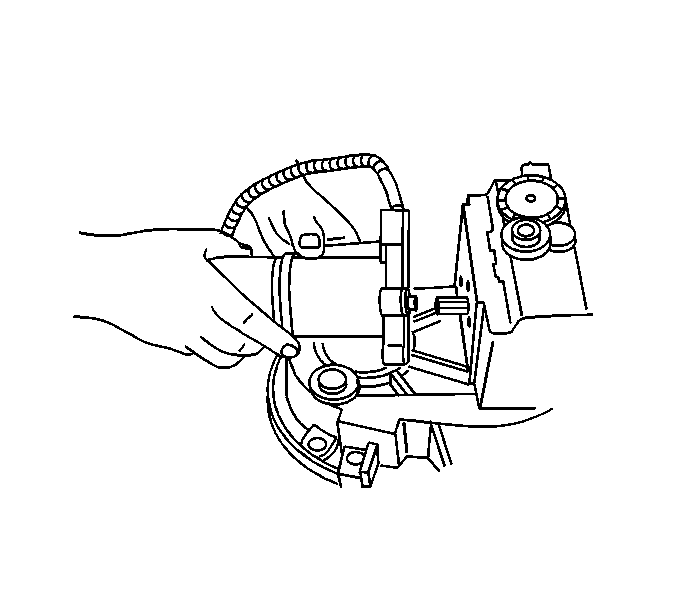
- Remove the encoder/motor mounting bolts.
- Remove the encoder/motor assembly.
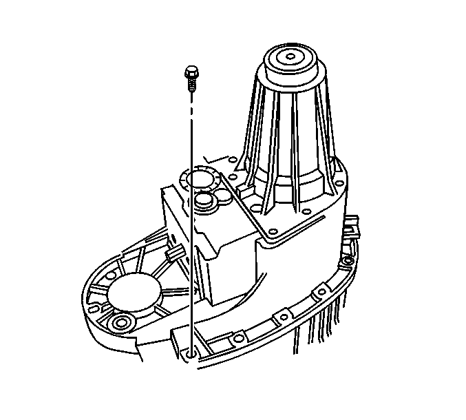
- Remove the rear extension mounting bolts.
- Remove the case half bolts.
- Install the J 45358 between the tabs on one side of the case.
- Using the J 45358 , shear the sealer securing the front and rear case half together.
- Move the J 45358 to the tabs on the other side of the case and shear the sealer.
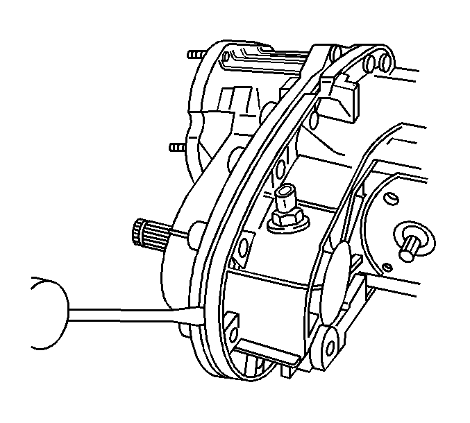
- Use a suitable prying tool at one side of the case half.
- Use a suitable prying tool at the other side of the cased halves.
- Working both tools, separate the front output shaft from the front output shaft bearing, and the input shaft from the output shaft.
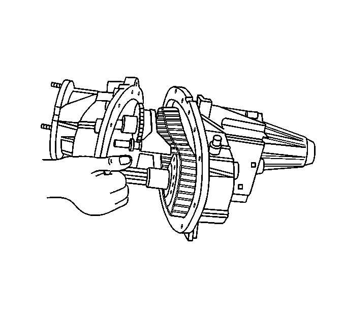
- Remove the front case half from the rear case half. Only the input gear assembly will remain with the front case half.
- Remove the front output shaft from the front output shaft rear bearing.
- Remove the drive chain assembly from the drive gear on the output shaft, and the driven gear on the front output shaft.
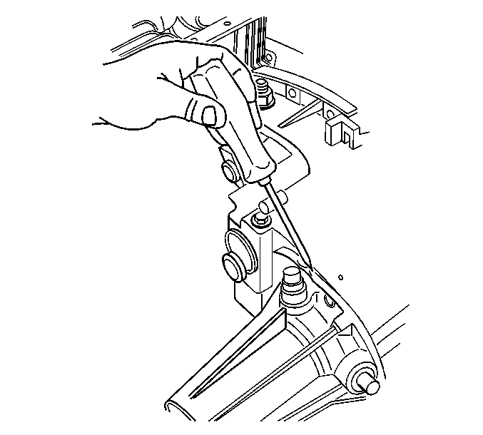
- Insert a screw driver in the slot of the rear extension.
- Remove the rear extension from the rear case half.
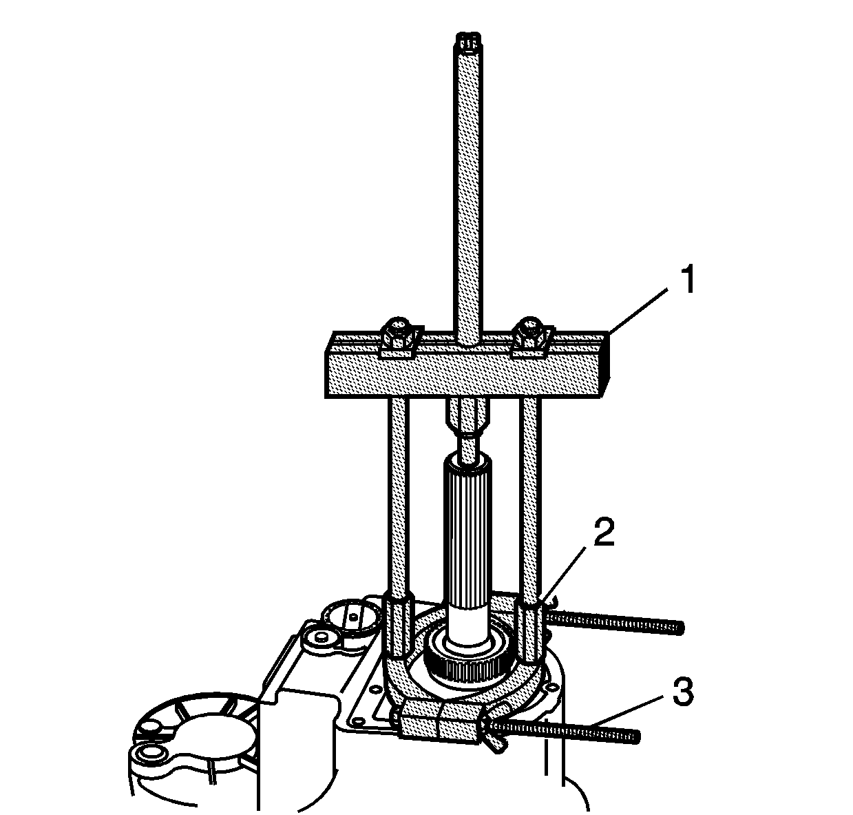
- Using the J 44707 (1), the J 44759 (2), and the J 36513 (3), remove the speed sensor reluctor wheel from the rear output shaft.
- Discard the speed sensor reluctor wheel after removal.
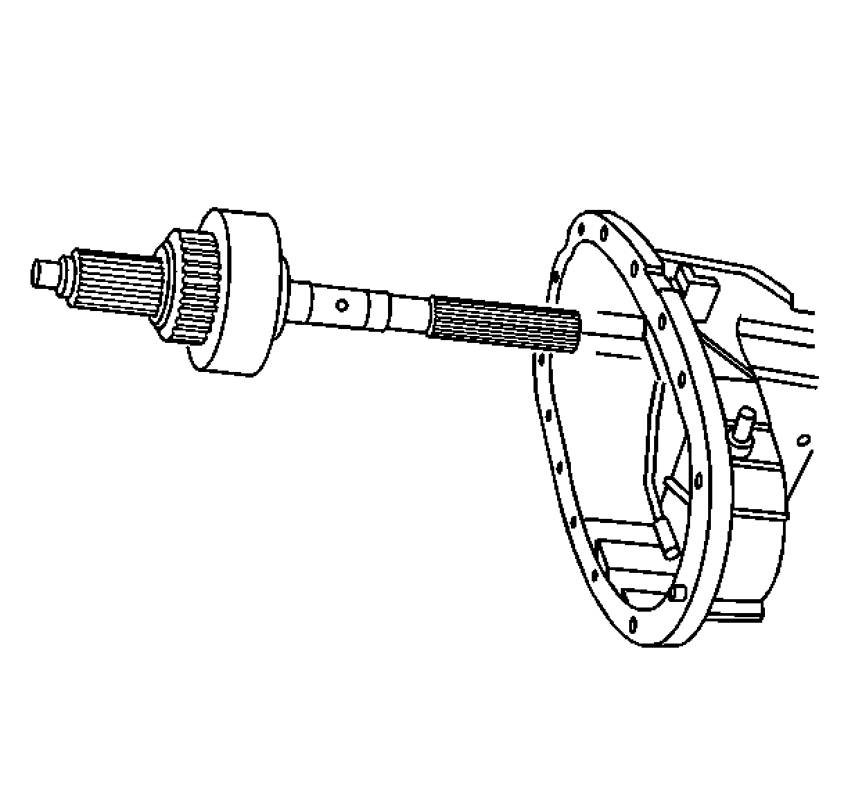
- Remove the rear output shaft assembly.
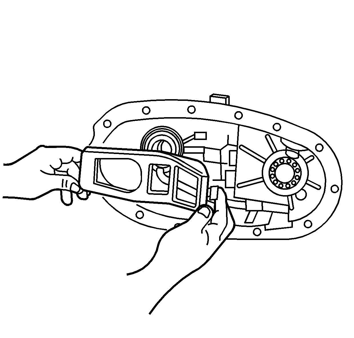
- Remove the clutch lever from the rear case half.
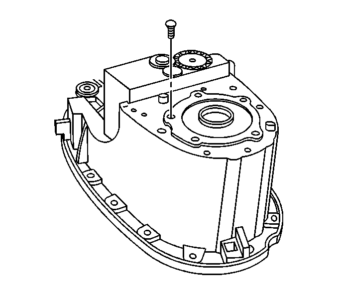
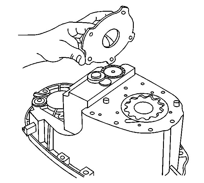
- Remove the oil pump cover mounting bolts.
- Remove the oil pump cover.
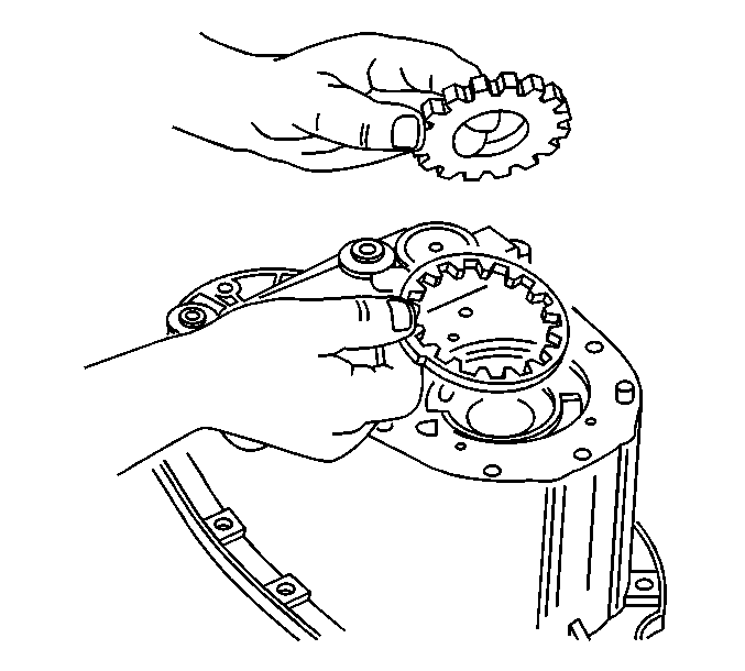
- Remove the oil pump drive gear, the inner rotor.
- Remove the oil pump driven gear, the outer rotor.
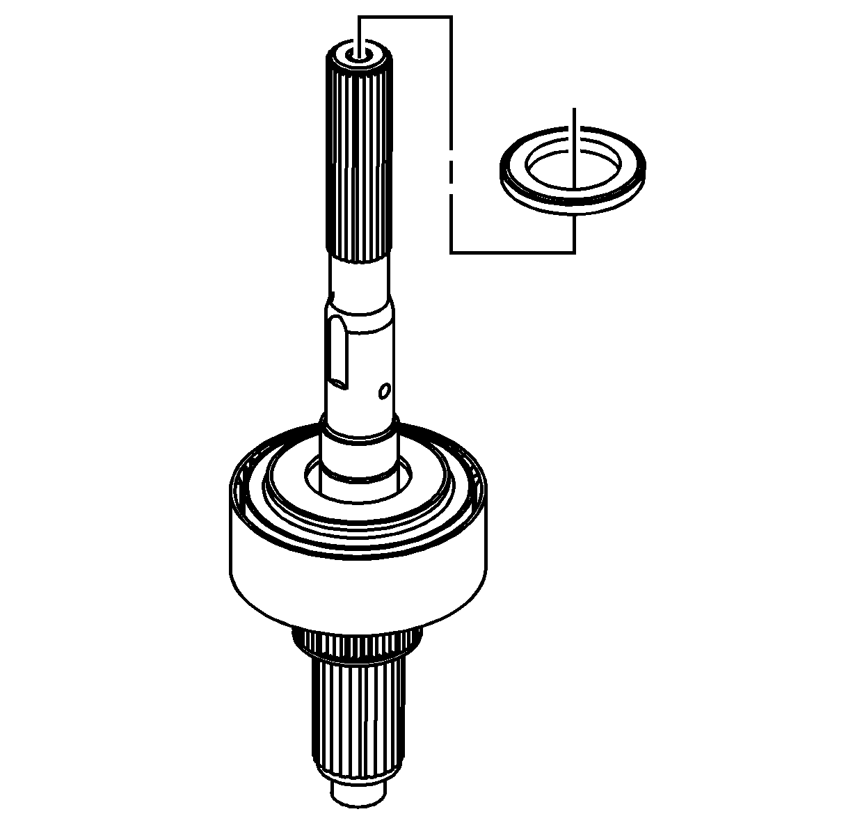
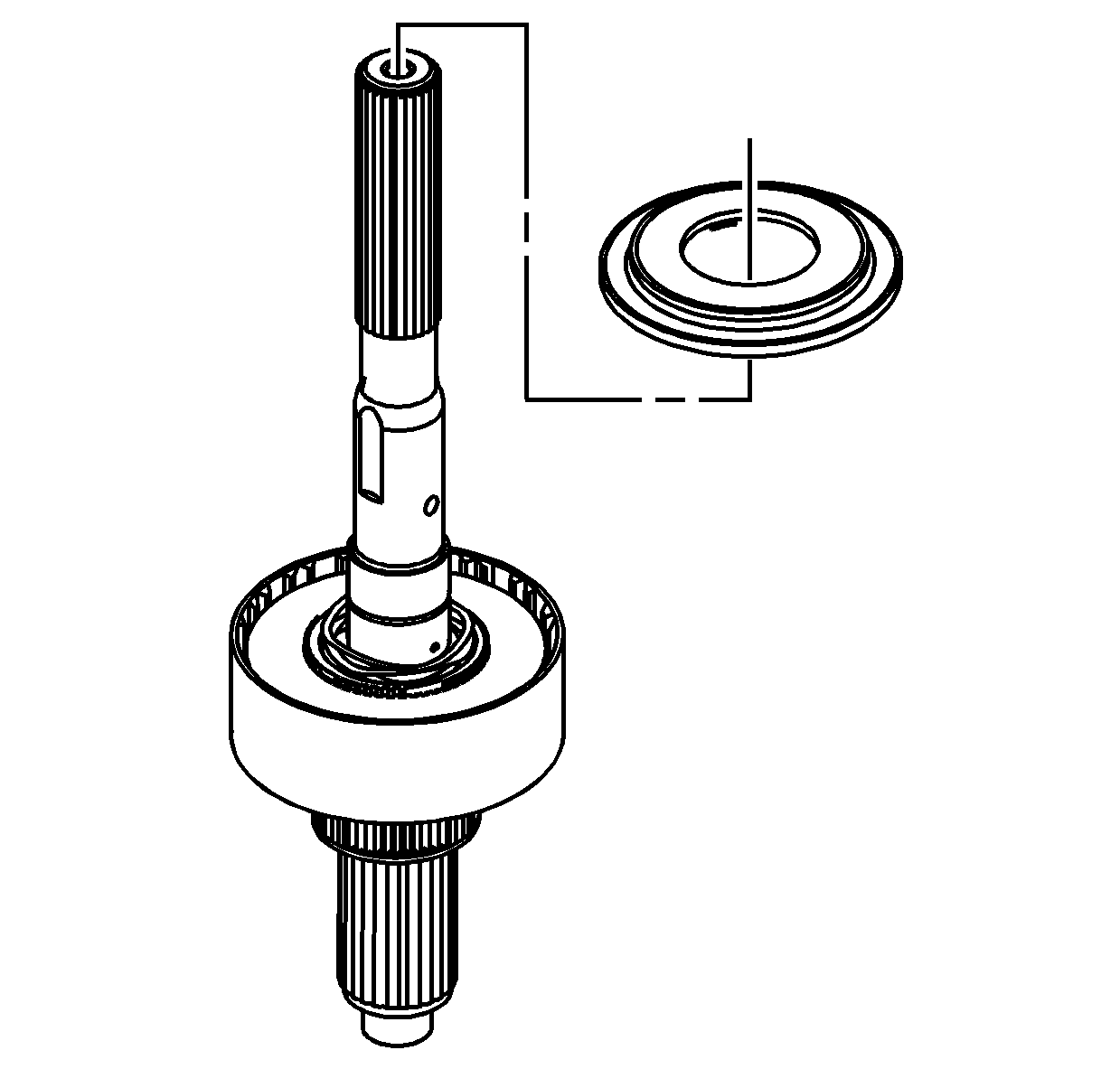
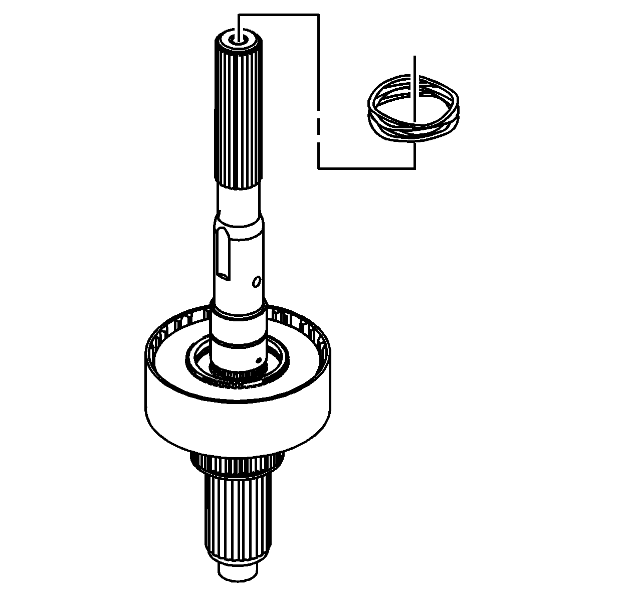
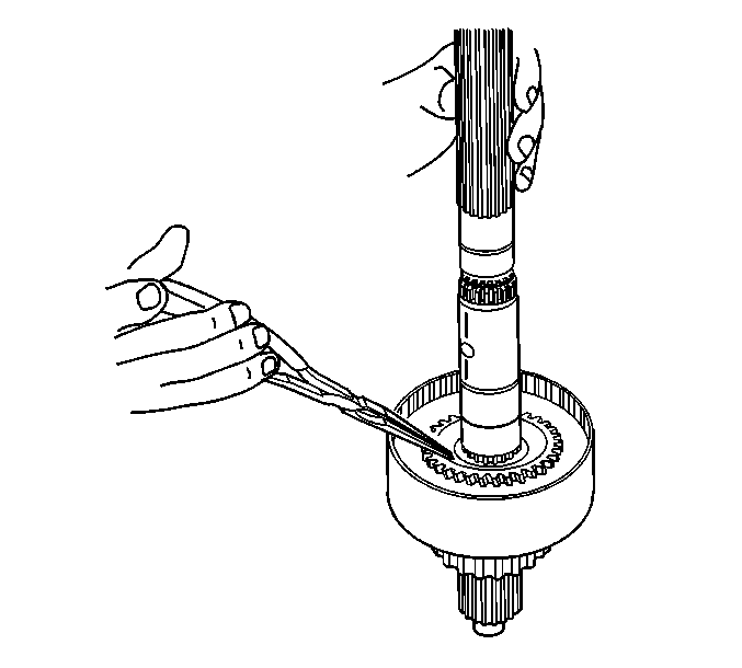
- While pushing down on the clutch apply plate, remove the clutch pressure plate bearing retaining ring.
- Remove the clutch inner plate.
- Remove the clutch pressure plate bearing.
- Remove the clutch apply plate.
- Remove the clutch spring.
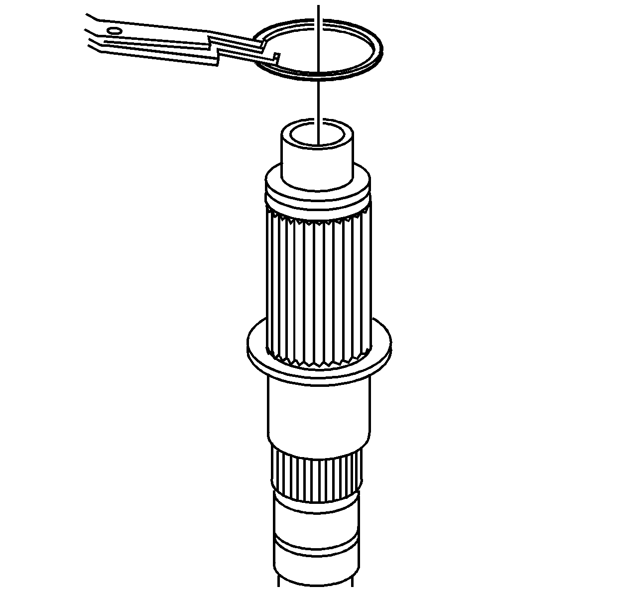
- Remove the clutch hub retaining ring.
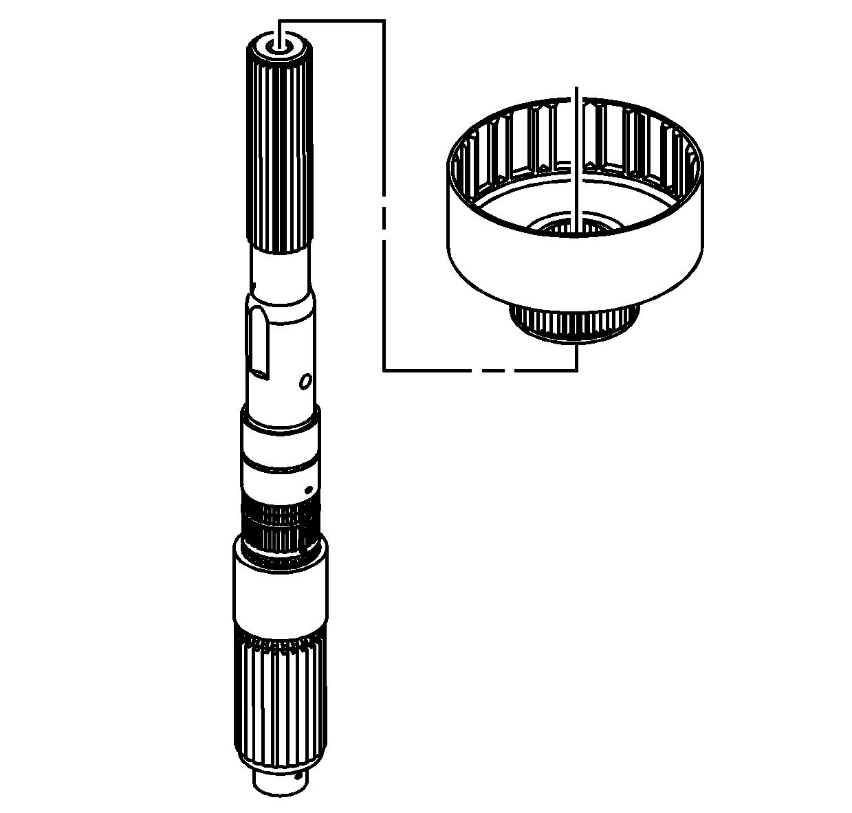
- Remove the clutch housing assembly.
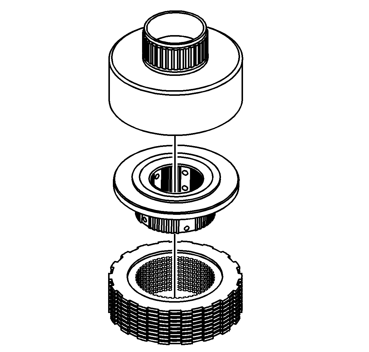
- Hold on to the clutch plates, and turn the clutch housing over on a work bench.
- Remove the clutch housing from the clutch plates and the clutch hub.
- Remove the clutch hub from the clutch plates.
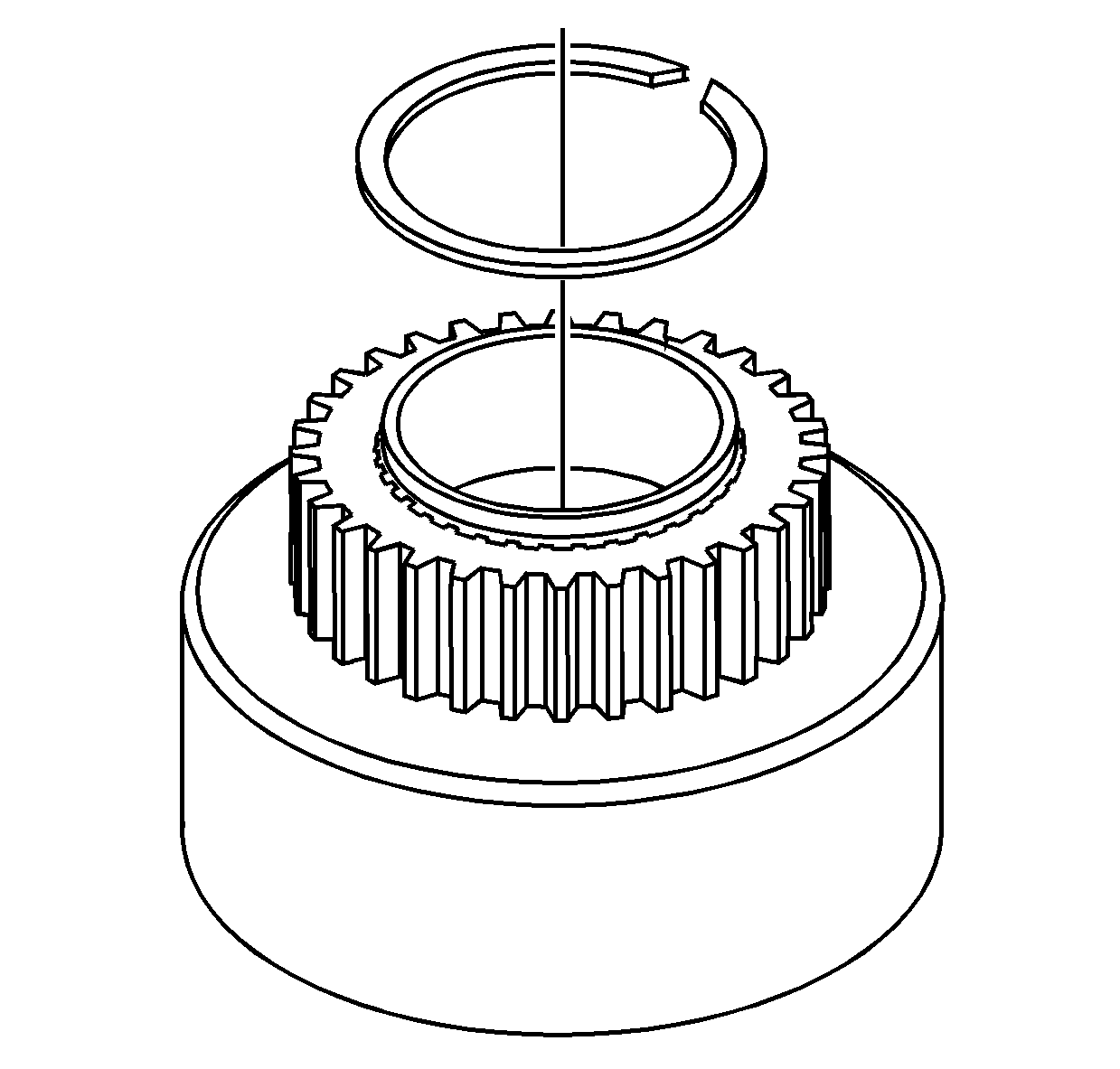
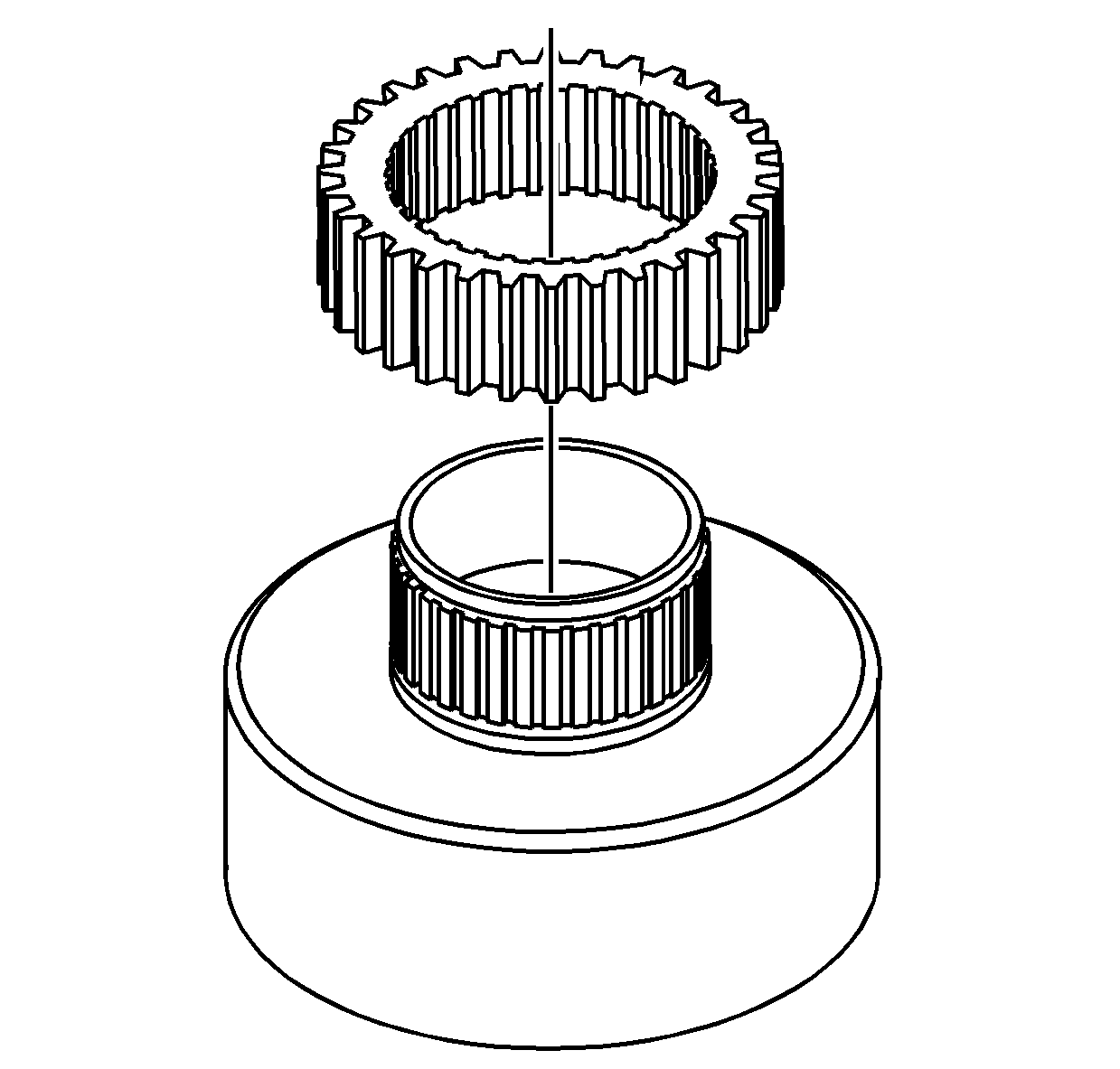
- Remove the drive sprocket retaining ring from the clutch housing.
- Remove the drive sprocket from the clutch housing.
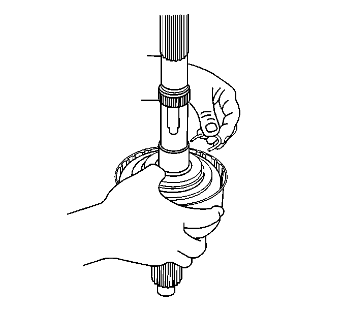
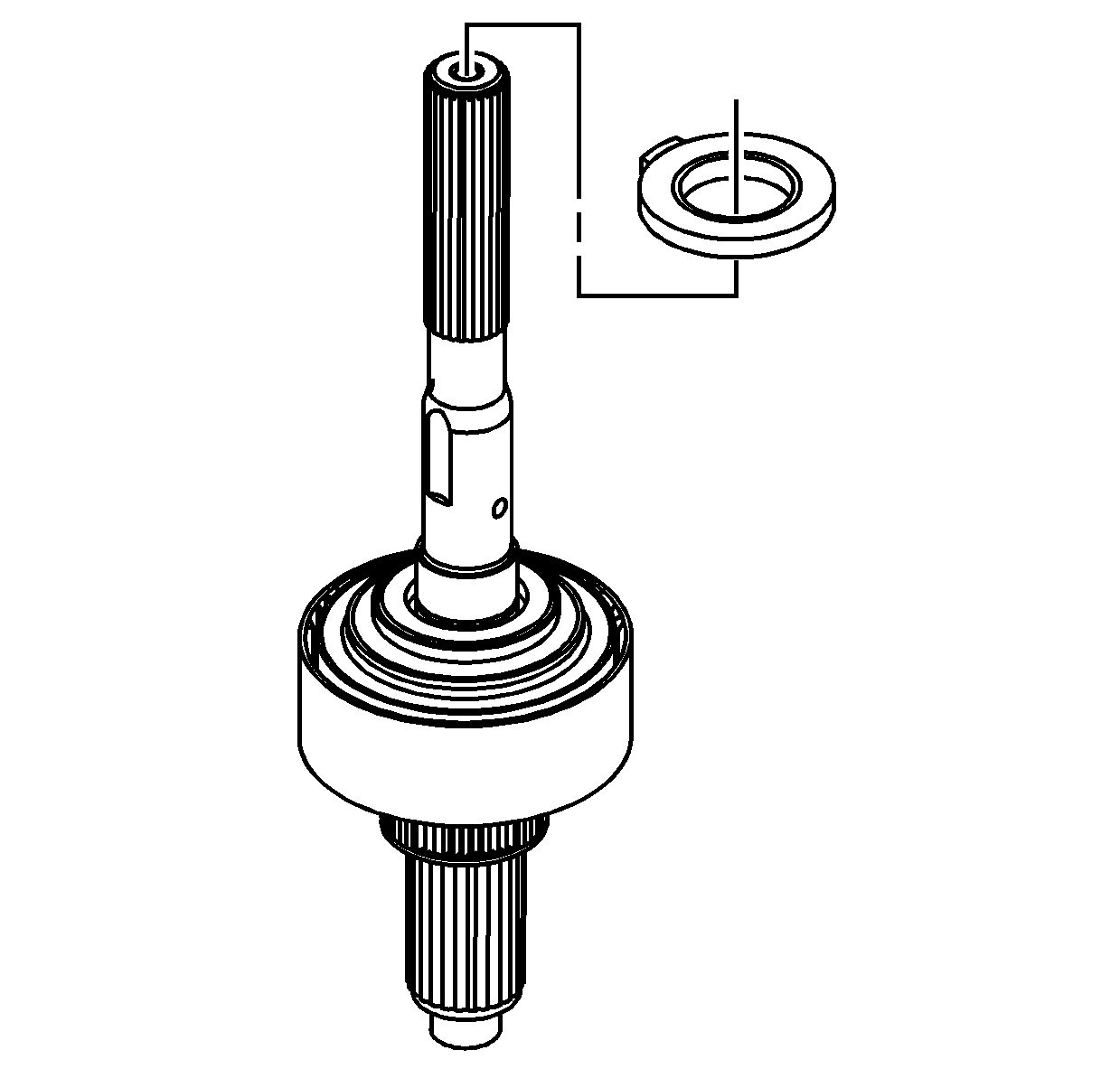
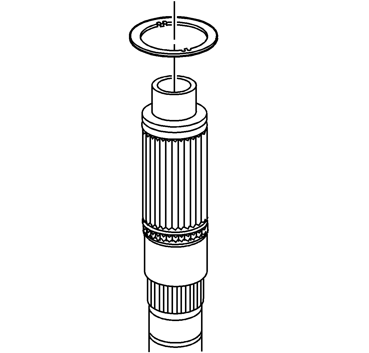
- Remove the clutch housing retaining ring from the rear output shaft.
- Remove the rear output shaft rear thrust washer.
- Using a press, remove the input gear.
- Using a press, remove the input gear bearing.
- If necessary, remove the input gear thrust bearing from the input gear.
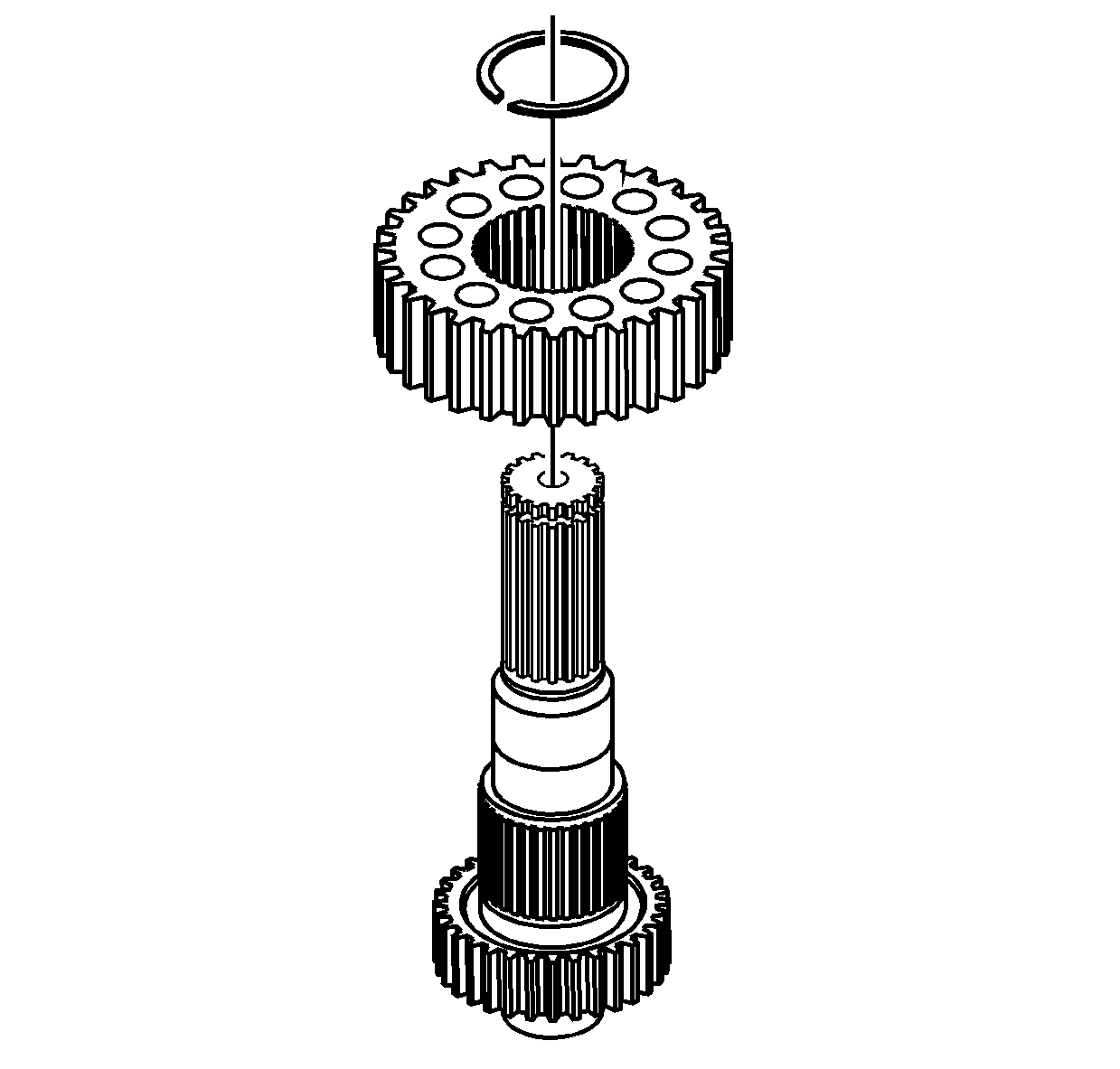
- Remove the driven gear retaining ring from the front output shaft.
- Remove the driven gear from the front output shaft.
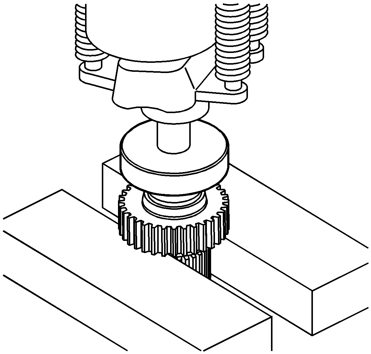
- Using a hydraulic press and a suitable adapter on the front input shaft, remove the front speed sensor reluctor wheel.
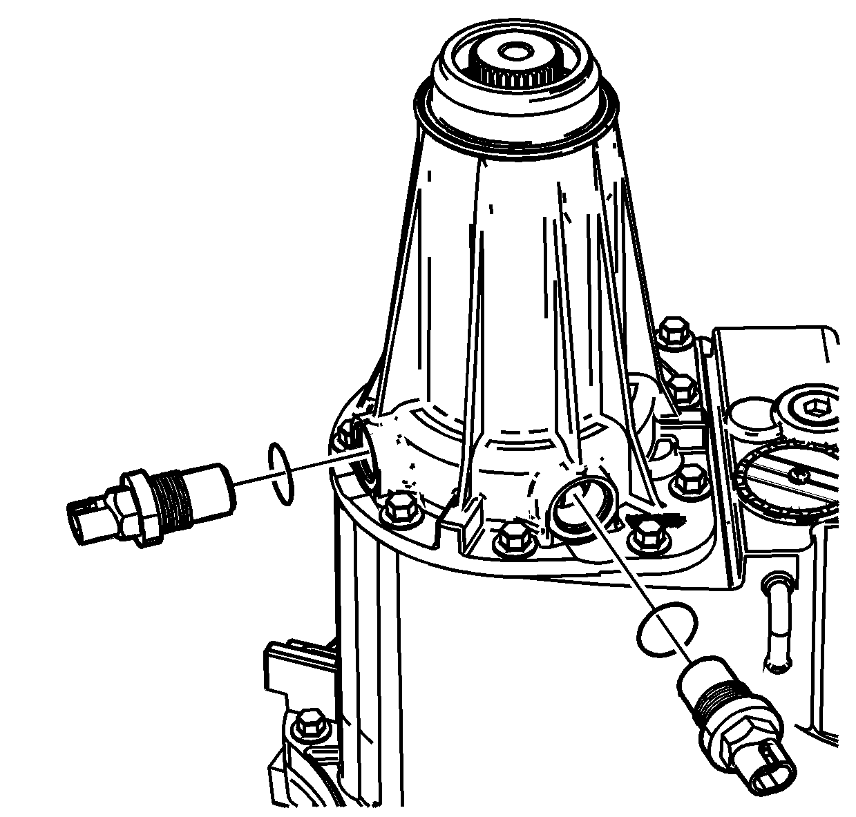
- Remove both vehicle speed sensors (VSS) and O-ring seals from the rear extension.
- Using a hammer and a punch, remove the rear output shaft seal.
- Remove the vent.
- Remove the front output shaft VSS and O-ring seal from the rear case.
- Remove the chip collector magnet from the rear case.
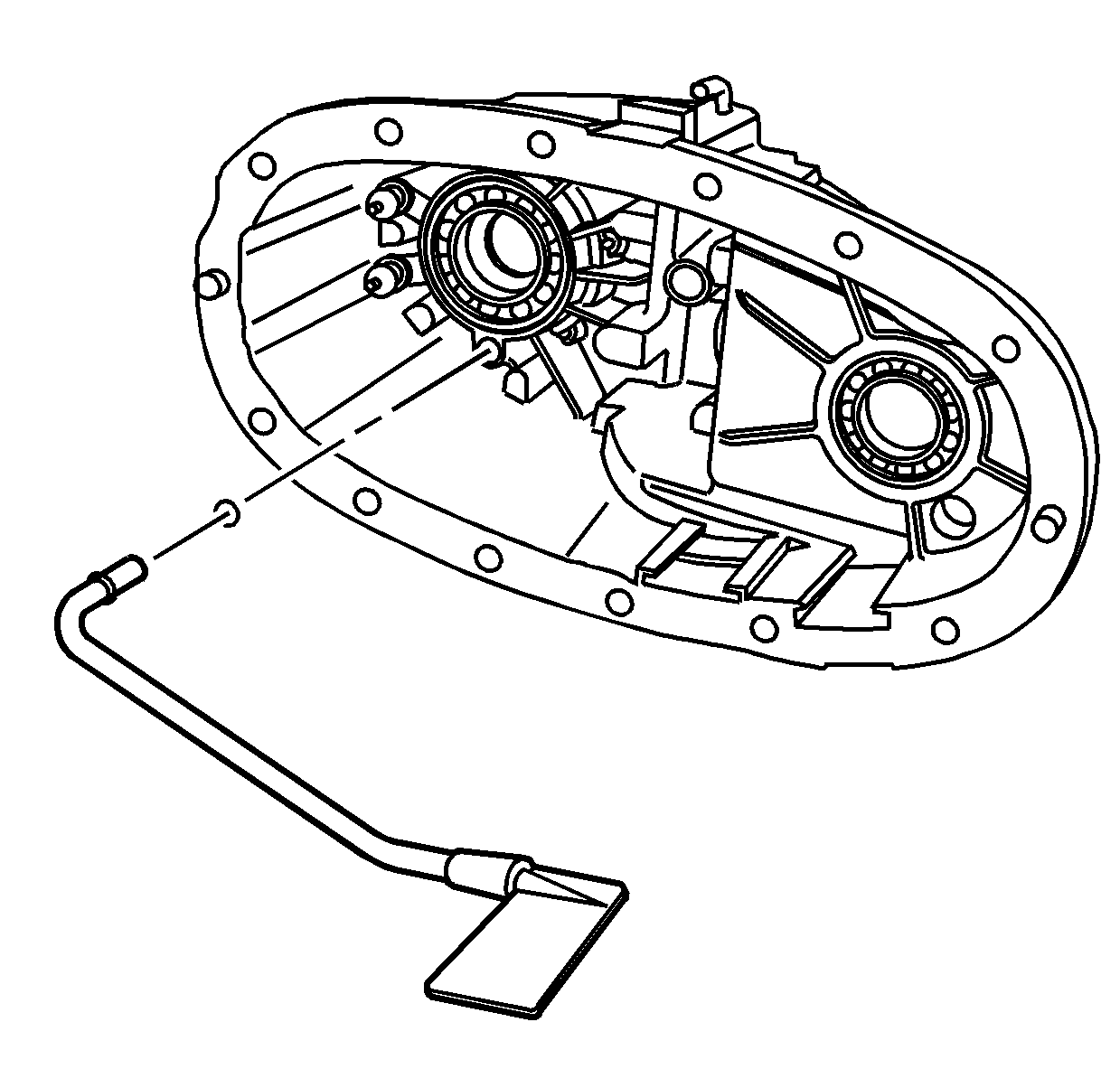
- Remove the oil pump suction pipe with the oil pump screen.
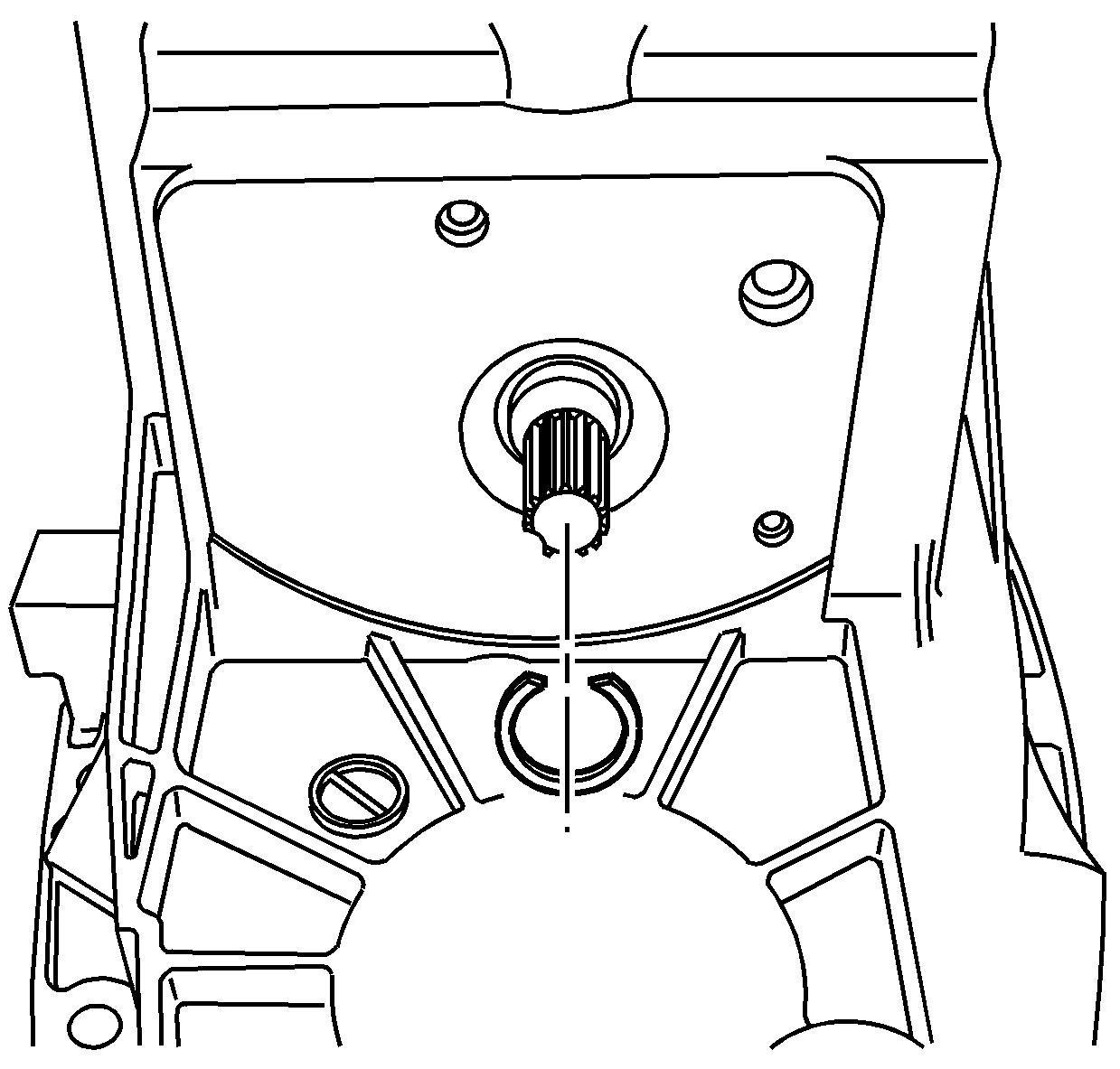
- Remove the retaining ring for the control actuator lever shaft.
- Discard the retaining ring.
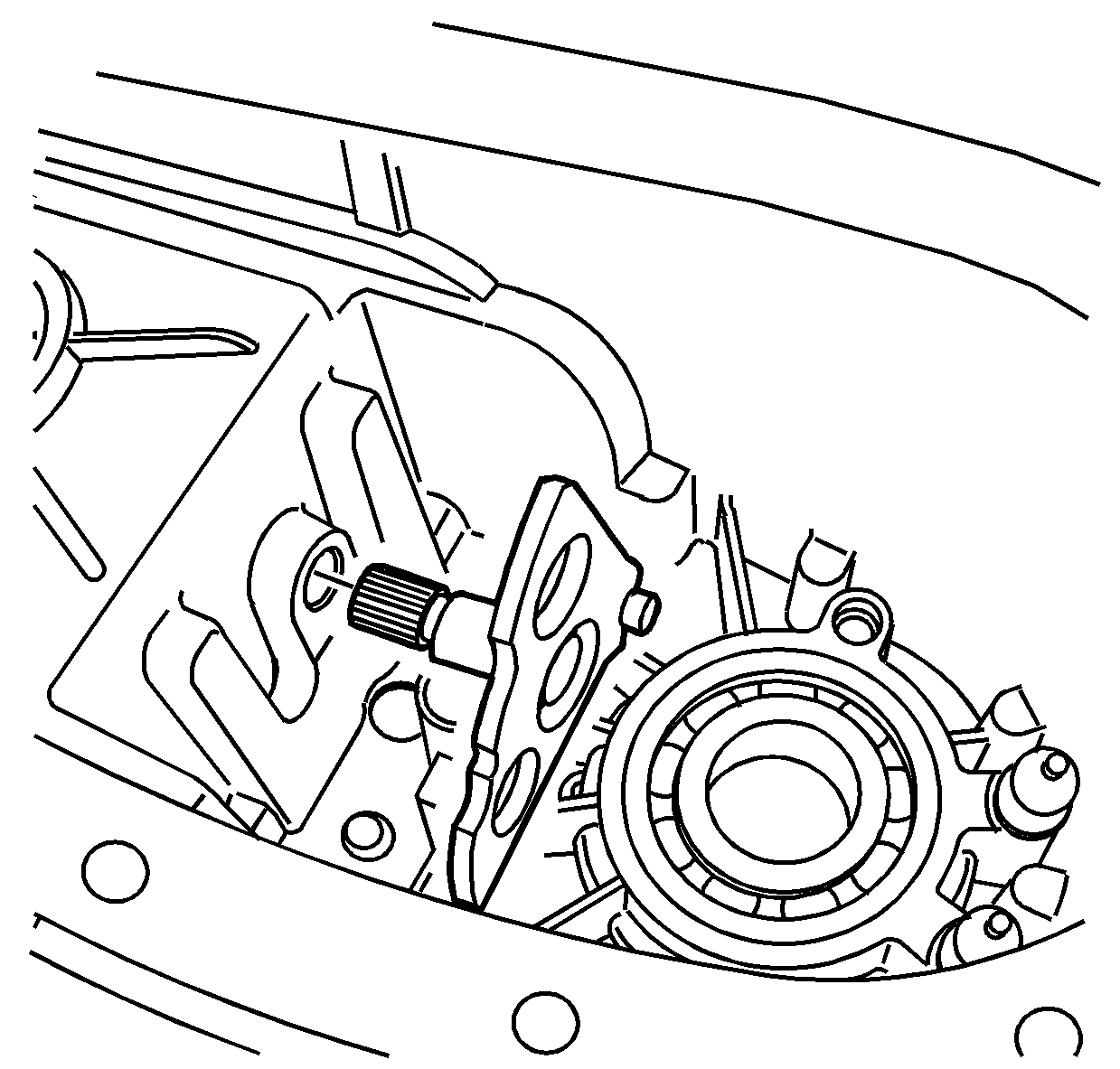
- Remove the control actuator lever shaft from the rear case.
- Inspect the front output shaft rear bearing for being faulty. Refer to Transfer Case Cleaning and Inspection.
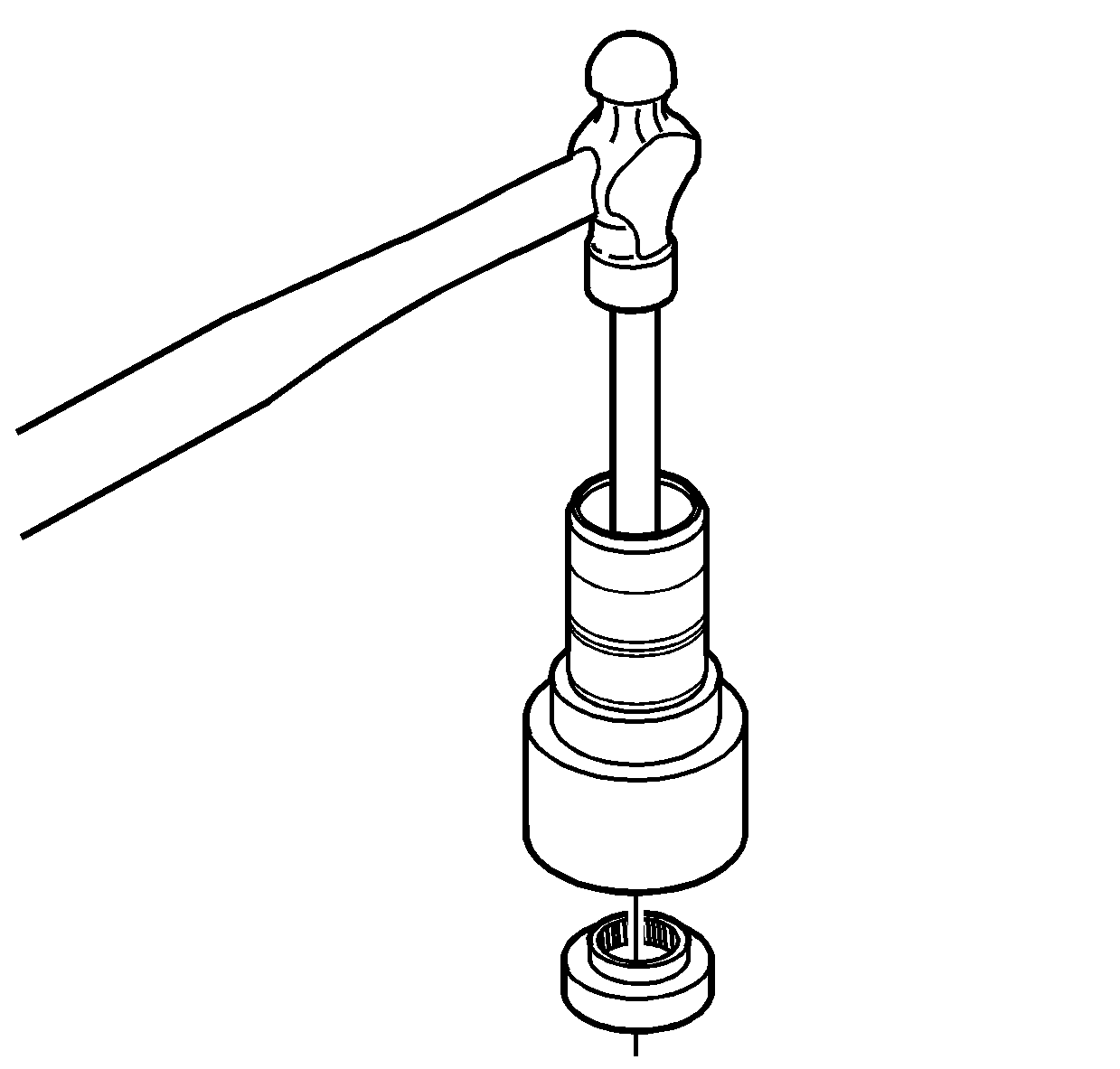
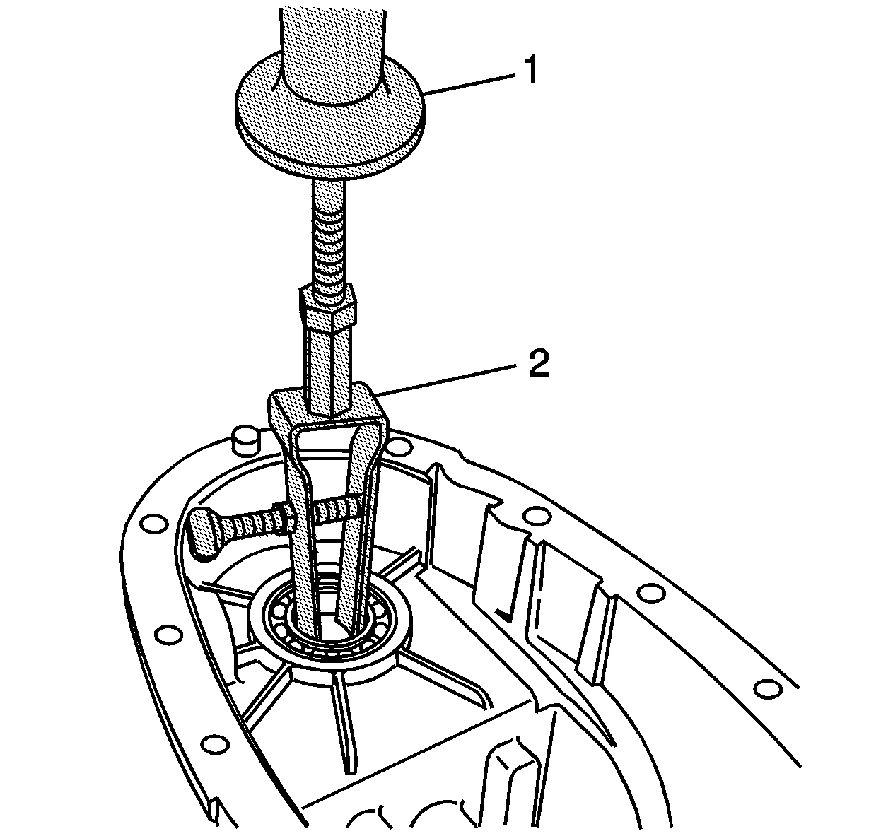
- Using the J 23907 (1) and the J 26941 (2), remove the rear bearing for the front output shaft.
- Inspect the rear output shaft bearing for being faulty. Refer to Transfer Case Cleaning and Inspection.
- Using the J 23907 (1) and the J 26941 (2), remove the rear output shaft bearing from the rear case. Ensure the jaws on the J 26941 are between the bearing and the oil pump bushing.
- Inspect the control actuator lever shaft bearing for being faulty. Refer to Transfer Case Cleaning and Inspection.
- Using the J 44707 (2) and the J 44737 (1), remove the control actuator lever shaft bearing.
- Using a suitable prying tool, remove the front output shaft seal.
- Discard the seal.
- Inspect the front output shaft front bearing for being faulty. Refer to Transfer Case Cleaning and Inspection.
- Using a hammer and a punch, remove the front bearing, for the front output shaft, from the front case.
- Clean and inspect all the internal parts of the transfer case. Refer to Transfer Case Cleaning and Inspection.
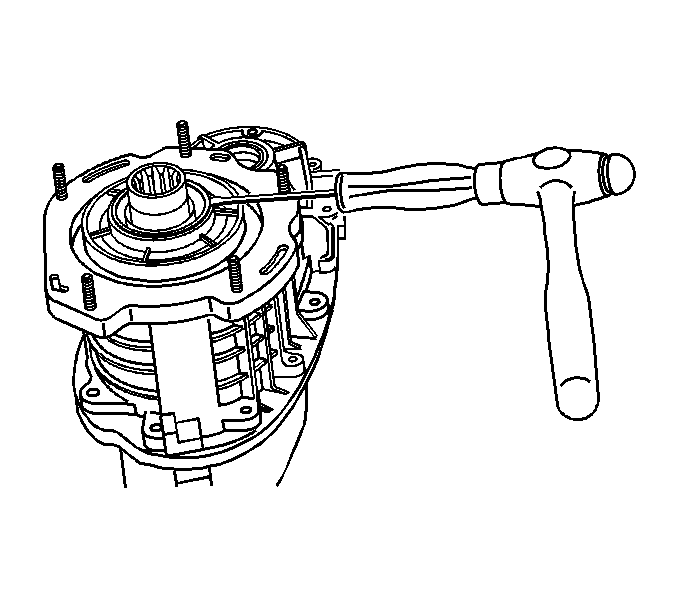
Notice: Do not damage the sealing surfaces of the transfer cases or the shafts when prying the seals for removal. Damaging the sealing surface may cause leakage or require replacement of the damaged component.
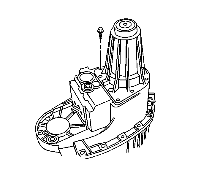
Important: Remove the rear extension and case half bolts at the same time for easier rear case disassembly.
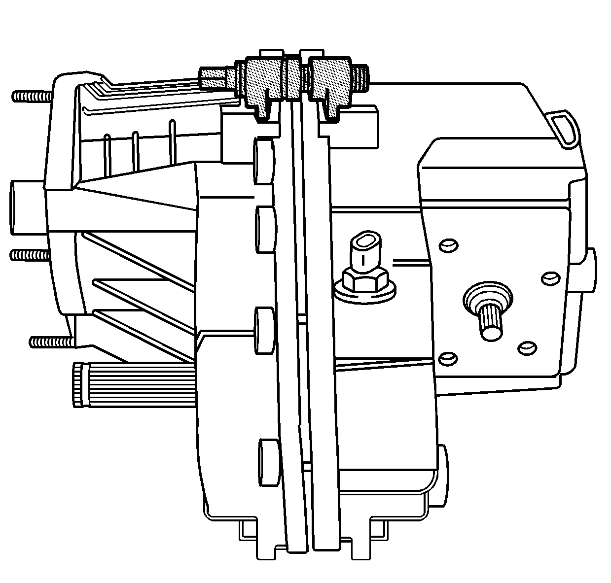
Notice: Do not nick, scratch or damage the sealing surface. The sealing surface is a machined surface. Damage to the machined surface can cause leakage.
Important:
• Ensure that all of the case half bolts have been removed. • DO NOT use screwdrivers or pry bars to separate the transfer case halves. The special tool must be used to separate the transfer case halves properly.
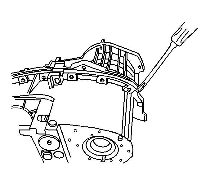
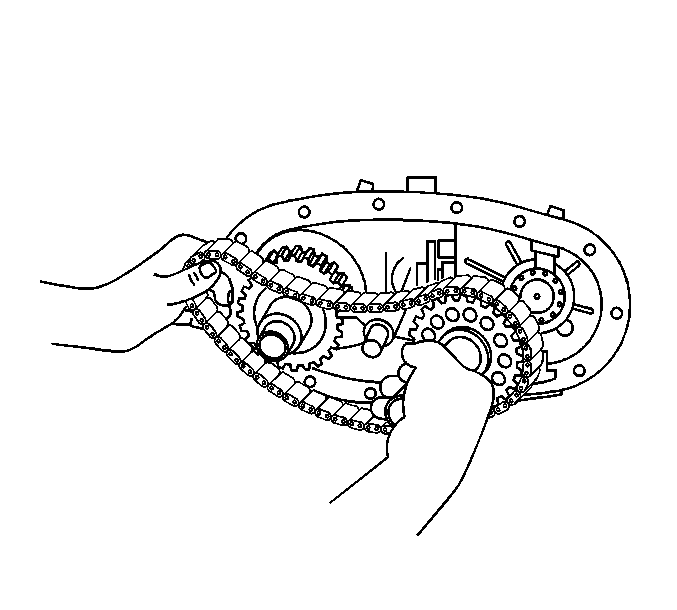
Important: If reusing the drive chain and sprockets, mark the position of the drive chain to the sprockets in order for the proper wear pattern alignment.
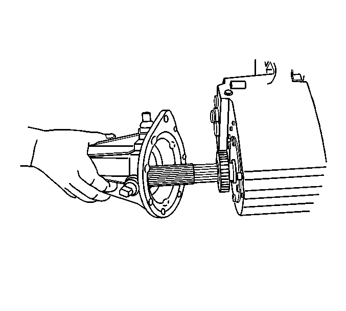
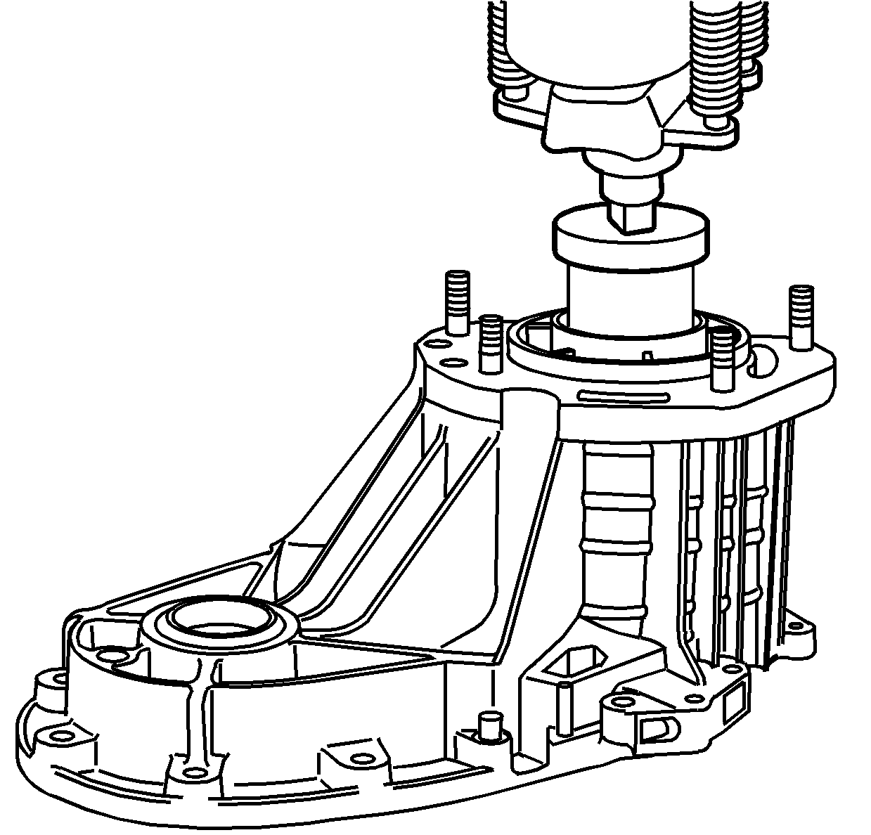
| 46.1. | Support the front case half on press plates to allow the input gear removal. |
| 46.2. | Use a suitable adapter to press on the input gear. |
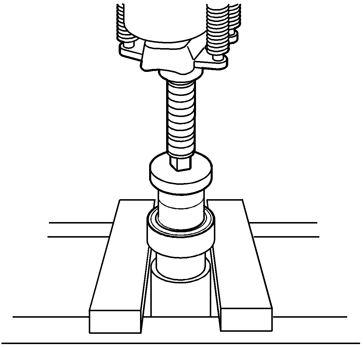
Important: The input gear bearing may come out with the input gear, or it may remain in the case. If the input gear bearing comes out with the input gear, use the following procedure:
Notice: Do not damage the sealing surfaces of the transfer cases or the shafts when prying the seals for removal. Damaging the sealing surface may cause leakage or require replacement of the damaged component.
The rear extension bushing is not serviceable.
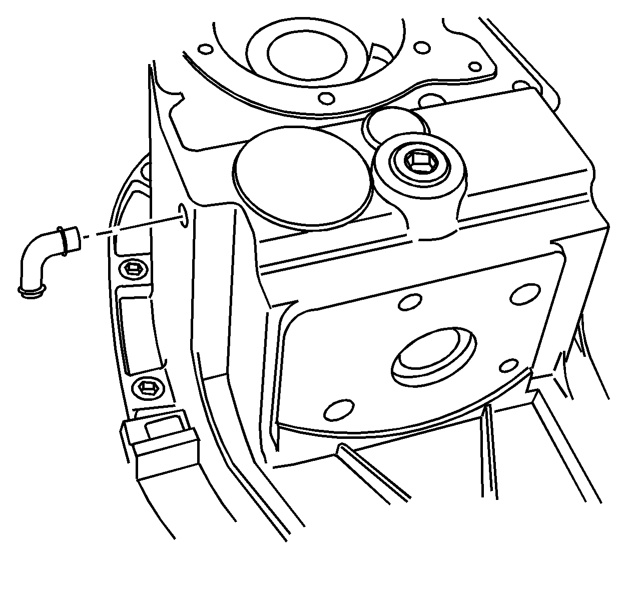
Important: The vent only requires removal if it is damaged.
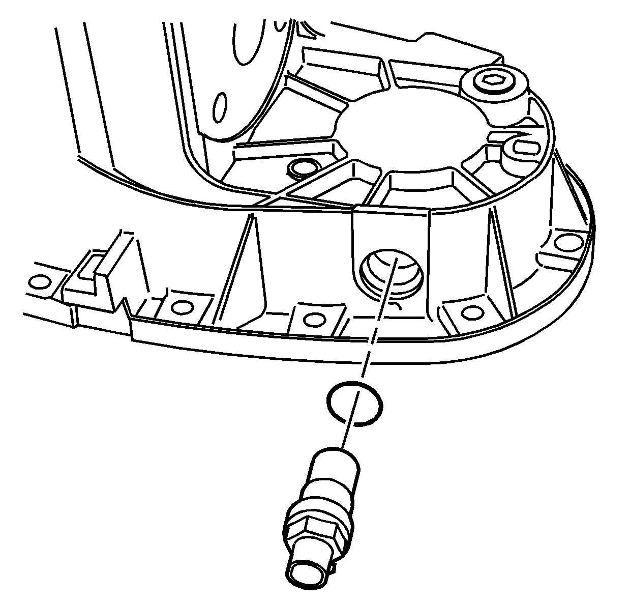
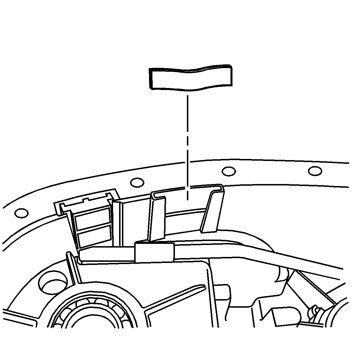
Important: Only remove the bearings if they are faulty. Do not reuse the bearings.
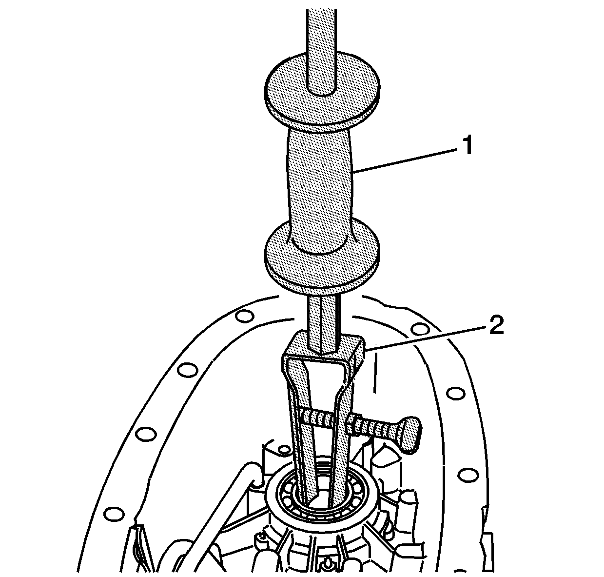
Important: Only remove the bearings if they are faulty. Do not reuse the bearings.
Important: The bushing surface for the oil pump is located by the output shaft bearing. When using the J 26941 , the jaws must not come in contact with the oil pump bushing surface.
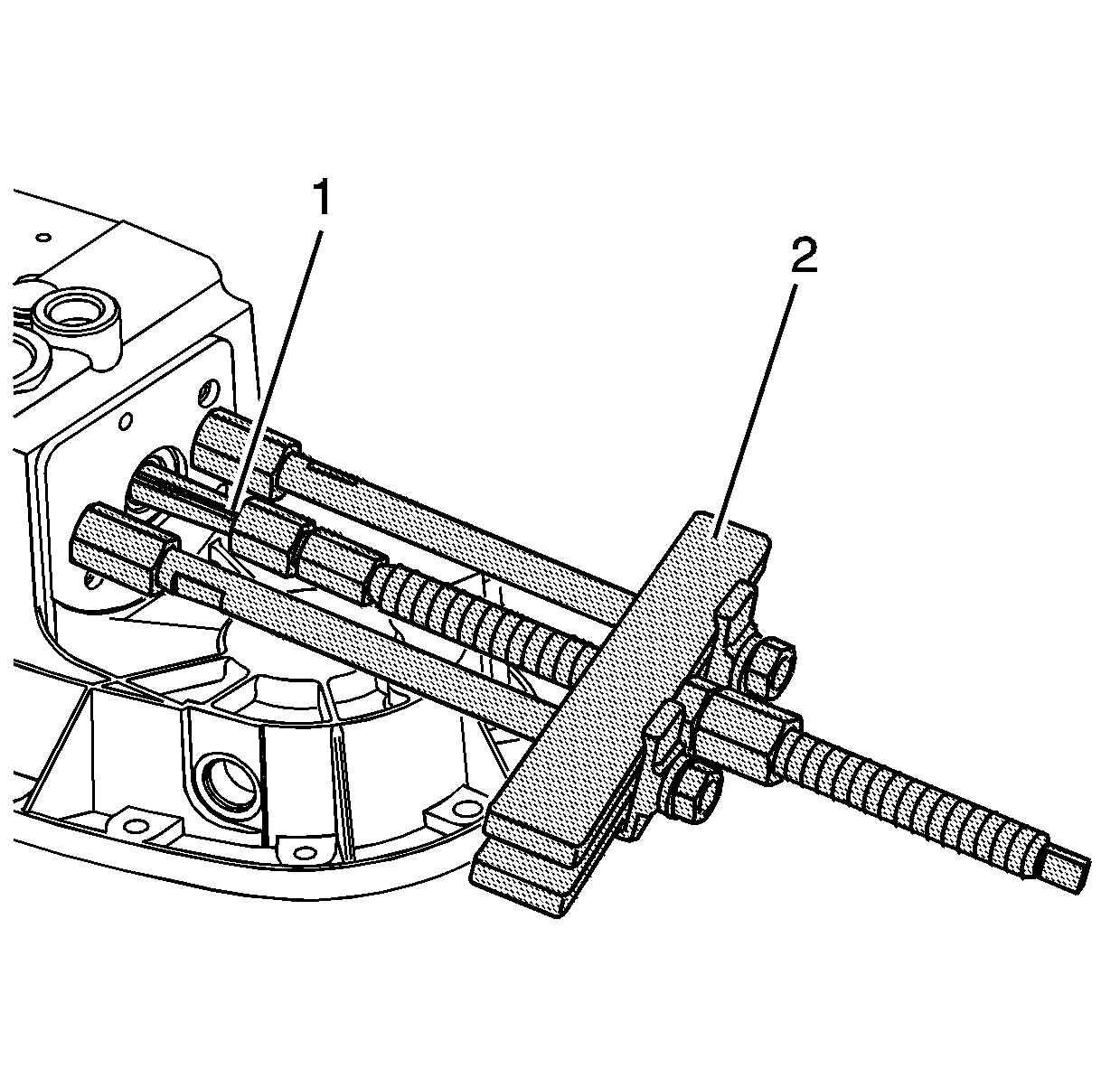
Important: Only remove the bearings if they are faulty. Do not reuse the bearings.
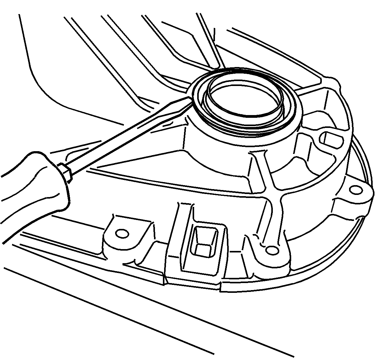
Notice: Do not damage the sealing surfaces of the transfer cases or the shafts when prying the seals for removal. Damaging the sealing surface may cause leakage or require replacement of the damaged component.
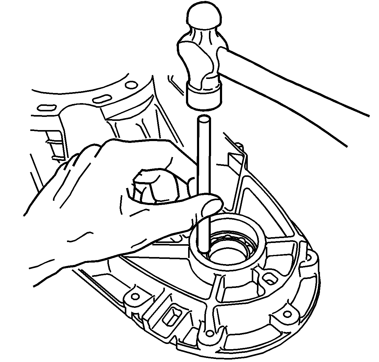
Important: Only remove the bearings if they are faulty. Do not reuse the bearings.
