DIESEL BLACK SMOKE ACCELERATE SERVICE & DIAGNOSIS OF EGR

MODELS: ALL MODELS WITH 6.2L DIESEL (R.P.O. CH6 - LIGHT DUTY EMISSIONS)
Heavy black exhaust smoke, upon acceleration, generally indicates a malfunction in the EGR system. To take corrective action, the operation of the 6.2L diesel EGR system must be understood to properly diagnose EGR related malfunctions.
EXHAUST GAS RECIRCULATION SYSTEM (EGR)
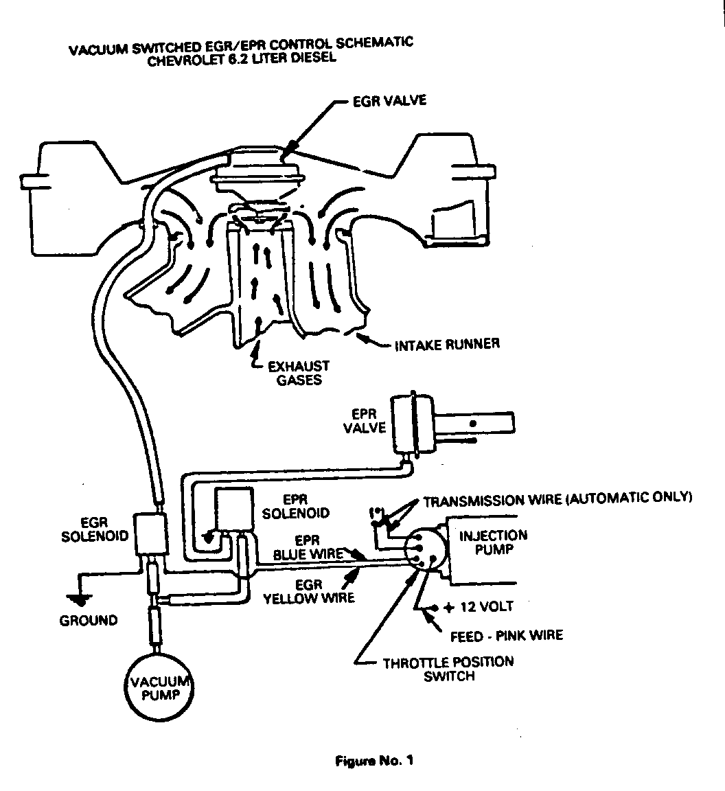
Exhaust gas is recycled through the combustion cycle by admitting exhaust gases into the intake manifold. Exhaust gases are routed from both cylinder heads through internal passages in the manifold to the EGR valve (Figure No. 1). Exhaust gas flow is a function of the pressure differential between the exhaust system and the intake manifold. The EGR valve controls the exhaust flow at the point of discharge into the intake manifold.
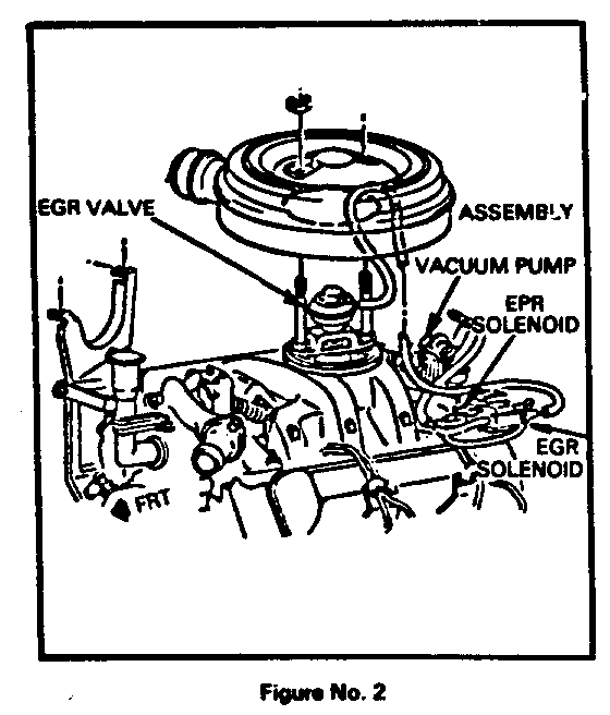
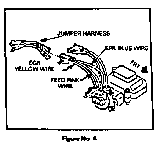
The EGR valve is operated by vacuum furnished from a mechanically driven vacuum pump (Figure No. 2). The vacuum source signal is routed through an electrically operated open/close solenoid (Fig ure No. 2) to the EGR valve. EGR is admitted into the intake manifold at idle, and light load fueling rates. The EGR valve remains fully open through a calibrated throttle lever motion. Throttle position is sensed by an electrical switch mounted directly to the R.H. side of the injection pump (Figure No. 4). As the throttle is opened, the throttle position switch (TPS) electrically closes at the calibration point, energizes the solenoid, and shuts off the vacuum signal, allowing the EGR valve to close.
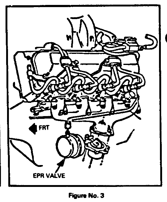
To increase flow EGR rates, an exhaust pressure regulator (EPR) valve (Figure No. 3) in used at the left hand exhaust manifold to increase exhaust back pressure. At closed throttle, the EPR valve is closed. With increasing throttle position, the throttle position switch electrically opens causing the EPR valve to open by shutting off vacuum to the valve. The EPR valve is controlled by its own switch point within the throttle position switch assembly and its own open/close solenoid (Figure No. 2). With automatic transmission vehicles, the throttle position switch has an additional function of locking and unlocking the transmission converter when the throttle is operated to a calibrated point.
When deactivated, the EGR valve is normally closed and the EPR valve is normally open.
Summarizing the EGR/EPR valve and solenoid operations:
Engine EGR EGR Speed Valve EGR Sol. Valve EPR Sol.
Not Idle to Energized Energized 15 DEG (Vacuum (Vacuum to Throttle Open to Valve) Closed Valve)
Not 15 DEG to Energized Not Energized 20 DEG (Vacuum (No Vacuum to Throttle Open to Valve) Open Valve)
20 DEG Energized Not Energized Full (No Vacuum (No Vacuum to Throttle Closed to Valve) Open Valve)
Heavy black exhaust smoke upon acceleration generally indicates a malfunction in the EGR system.
EGR/EPR DIAGNOSIS
1. Start engine and operate to open thermostat temperature.
2. Remove air cleaner cover to observe operation of EGR valve (Figure No. 2).
3. With engine at idle, the EGR valve should be open. (Observe valve head in up position and noticeable exhaust noise in intake). If not, check and correct any electrical and hose connections which may be loose and/or dis- connected.
4. Remove vacuum hose from EGR valve. The valve head should drop with a noticeable reduction in noise. Reconnect hose.
5. At idle, the hose to the EGR valve should have approximately 20 inches of vacuum. If vacuum is not present, check output of the vacuum pump at the pump. The pump should produce a minimum of 20 inches of vacuum.
6. If vacuum is present at the EGR valve but the valve does not open and close as the hose is put on and taken off, the EGR valve is stuck and should be checked and replaced if necessary.
7. Manually operate the throttle lever at the injection pump through approximately 15 DEG to 20 DEG of travel. The EGR valve should close when the TPS reaches the calibrated point.
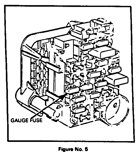
8. Check the pink wire to the TPS for 12 volts (key on). If 12 volts is not present, check for any loose connections, open wire, and a blown 20 amp gauge fuse.
9. Correct any loose wire connections and change fuse if required. With key on, the blue wire from the TPS switch should also have 12 volts. This blue wire feeds the EPR solenoid. At idle, if the pink wire has 12 volts but the blue one doesn't, the TPS is inoperative and should be changed per 1982 Light Duty Shop Manual procedure.
10. With engine off but key on, operate the throttle through 20 DEG travel. At approximately 15 DEG, the TPS will cut out the 12 volts to the blue wire (EPR). At approximately 20 DEG, the TPS will cut in 12 volts to the yellow wire (EGR). If not, the TPS is inoperative.
11. Check to see that the electrical connections are made at the EGR-EPR solenoid aseembly and that the hoses are routed correctly and connected to the solenoids.
12. If vacuum is present at the solenoid assembly and the solenoids are receiving an electrical signal as previously mentioned and operation of the TPS through the calibrated points does not operate the EGR and/or EPR valves, the solenoid assembly is inoperative and should be replaced.
DIODE CAUSING EGR SYSTEM MALFUNCTION
A condition exists whereby an excessive electrical feedback load can cause a diode in the EGR and/or EPR solenoids to short. The diodes are for radio noise suppression only. When the diode shorts it usually will blow the 20 amp gauge fuse. A blown fuse will result in no engine electrical accessory feed such as no glow plug operation or light, no cold advance or fast idle, and the EGR system will not operate. When the EGR system becomes inoperative, full vacuum is supplied to the EGR valve at all speeds resulting in heavy black exhaust smoke and low power.
To prevent the diodes from shorting due to heavy feedback loads, a jumper harness unit #14048052 is being made available too install in the EGR-EPR electrical feed circuit at the TPS. This jumper harness has a built in diode to reduce the feedback load (Figure No. 4).
If a comment of heavy black exhaust smoke is received and the condition can be traced to the EGR/EPR solenoid assembly diode, the following outlines the procedure to follow to install the jumper harness unit.
1. Have engine stopped and key in off position.
2. Disconnect vacuum and electrical connections to the EGR/EPR solenoid aseembly (Figure No. 2).
3. Remove bolt holding assembly, remove and install new asssembly.
4. Reconnect vacuum hose and electrical connections.
5. Disconnect (3) wire connector to TPS and install jumper harness between connectors. (NOTE - The wire colors blue, pink and yellow should line up.) (Figure No. 4).
6. Install a new 20 amp gauge fuse (Figure No. 5).
Use applicable labor operations.
General Motors bulletins are intended for use by professional technicians, not a "do-it-yourselfer". They are written to inform those technicians of conditions that may occur on some vehicles, or to provide information that could assist in the proper service of a vehicle. Properly trained technicians have the equipment, tools, safety instructions and know-how to do a job properly and safely. If a condition is described, do not assume that the bulletin applies to your vehicle, or that your vehicle will have that condition. See a General Motors dealer servicing your brand of General Motors vehicle for information on whether your vehicle may benefit from the information.
