DELCO FREEDOM BATTERY DIAGNOSIS AND CHARGING

MODELS: ALL GMC TRUCKS
GMC trucks may have several electrical devices which result in continuous current drains on their batteries. Batteries in vehicles not being used for an extended period may become discharged by these small current drains called parasitic loads.
Any battery discharged by parasitic loading and then allowed to stand in this condition for a period of time may not accept recharge readily. However, if properly recharged, most batteries will return to a good useable condition.
If the battery remains in a discharged condition for a prolonged period, it can become permanently damaged. Permanent damage to discharged batteries can also be accelerated by high temperatures.
Extremely discharged batteries can freeze at temperatures as high as +20 DEG F, and freezing can also cause permanent damage.
To prevent battery damage and difficulty in recharging, any vehicles that are not going to be in service within a 30-60 day period should have ground cables disconnected to remove the constant drain on the batteries. If this is not possible, batteries should be recharged periodically every 30-60 days until the green dot is visible.
The following information, obtained from Delco-Remy Division, contains procedures for Freedom Battery charging, testing and jump-starting.
CAUTION
All batteries generate hydrogen gas which is highly flammable. If ignited by a spark or flame, the gas may explode violently, causing spraying of acid, fragmentation of the battery and possible severe personal injuries. Wear approved eye protection. Battery fluid is a corrosive acid. Flush any contacted area with water immediately and thoroughly.
VISUAL INSPECTION
Check for obvious damage, such as cracked or broken case or cover, that is permitting loss of electrolyte. If obvious damage is noted, replace the battery. Determine the cause of damage and correct as needed. If battery terminals are severely damaged, such as loose, burned, or broken, replace- ment of the battery is recommended. Evidence of small amounts of electrolyte leakage, especially around the vent holes, does not necessarily indicate the battery is defective - the leakage could have been caused by overcharging or tipping of the battery.
READING BUILT-IN HYDROMETER
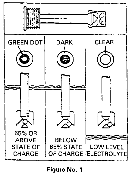
Look down into the built-in hydrometer (clean and use a flashlight if necessary) to observe its reading. (Refer to Figure No. 1)
GREEN DOT VISIBLE - Any green appearance is interpreted as a "green dot" and indicates that the battery is 65% or above state of charge and is ready for use or testing.
DARK, GREEN DOT NOT VISIBLE - Indicates the battery is below 65% state of charge and needs charging prior to testing.
CLEAR OR LIGHT YELLOW - This means the fluid level is below the bottom of the hydrometer. This may have been caused by excessive or prolonged charging, a cracked or broken case, excessive tipping, or normal battery wearout. Replace battery. Do not charge, test or jump-start. A dark reading may be misinterpreted as a clear or light yellow when inspecting a Freedom II battery. This is caused by light filtering through the new translucent case. Shake the battery to determine the fluid level and shield the battery sides from light to determine the true reading before replacing a battery.
BATTERY CHARGING
When charging a sealed battery, the following safety precautions must be followed:
Do not charge battery if hydrometer is clear or light yellow. Replace battery.
If the battery feels hot, 125, DEG F (50 DEG C), or violent gassing or spewing of electrolyte through the vent hole occurs, discontinue charging or reduce charging rate.
CHARGING PROCEDURE
1. Batteries with green dot showing do not require charging unless they have just been discharged (such as in cranking vehicle).
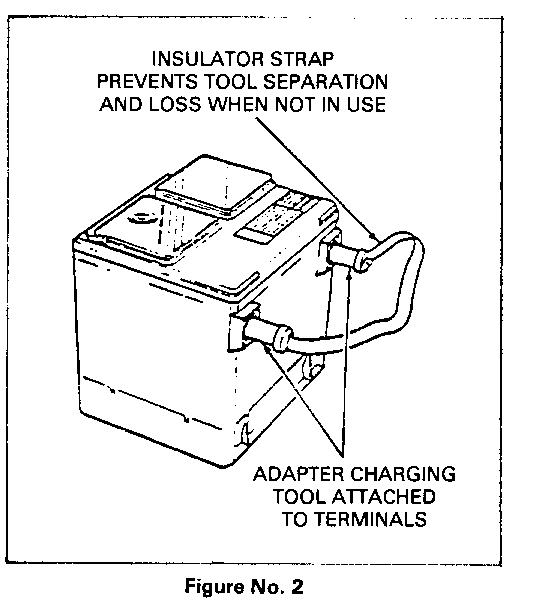
2. When charging sealed-terminal batteries out of vehicle, install adapter kit (AC Delco P/N ST- 1201 or GM P/N 1846855 or equivalent). (Refer to Figure No. 2) Post-type batteries need no adapters.
3. Make sure all charger connections are clean and tight.
4. For best results, batteries should be charged while electrolyte and plates are at room temperature. A battery that is extremely cold may not accept current for several hours after starting charger.
5. Charge battery until green dot appears. (See Charging Time Required). Battery should be checked every half-hour while charging. Tipping or shaking battery may be necessary to make green dot appear.
6. After charging, battery should be tested as outlined in "BATTERY TESTING", Page 6.
CHARGING TIME REQUIRED
The time required to charge a battery will vary dependent upon following factors:
SIZE OF BATTERY - A completely discharged large Heavy-Duty Battery requires more than twice the recharging as a completely discharged small Passenger Car battery.
TEMPERATURE - A longer time will be needed to charge any battery at 0 DEG F than at 80 DEG F. When a fast charger is connected to a cold battery, the current accepted by the battery will be very low at first, then in time the battery will accept a higher rate as the battery warms.
CHARGER CAPACITY - A charger which can supply only 5 amperes will require a much longer period of charging than a charger than can supply 30 amperes or more.
STATE-OF-CHARGE - A completely discharged battery requires more than twice as much charge as a one-half charged battery. Because the electrolyte is nearly pure water and a poor conductor in a completely discharged battery, the current accepted by the battery, is very low at first. Later as the charging current causes the electrolyte acid content to increase, the charging current will likewise increase.
CHARGING A VERY FLAT OR COMPLETELY DISCHARGED BATTERY (OFF THE VEHICLE)
The following procedure should be used to recharge a very flat or completely discharged battery:
Unless the procedure is properly followed, a perfectly good battery may be needlessly replaced.
1. Measure voltage at battery terminals with an accurate voltmeter. If below 10 volts, then the charge current will be very low and it could take some time before it accepts a current in excess of a few milliamperes.
Such low current may not be detectable on ammeters available in the field.
2. Set battery charger on high setting.
3. Some chargers feature polarity protection circuitry which prevents charging unless the charger leads are connected to the battery terminals correctly. A completely discharged battery may not have enough voltage to activate this circuitry, even though leads are connected properly, making it appear that the battery will not accept charging current. Therefore, follow the specific charger manufacturer's instruction telling how to by-pass or override the circuitry so that the charger will turn on and charge a low-voltage battery.
4. Battery chargers vary in the amount of voltage and current they provide. The time required for the battery to accept measurable charger current at various voltages may be as follows:
VOLTAGE HOURS
A. 16.0 or more Up to 4 hours B. 14.0 - 15.9 Up to 8 hours C. 13.9 or less Up to 16 hours
If the charge current is still not measurable at the end of the above charging times, the battery should be replaced.
If the charge current is measurable during the charging time, the battery is considered to be good and charging should be completed in the normal manner.
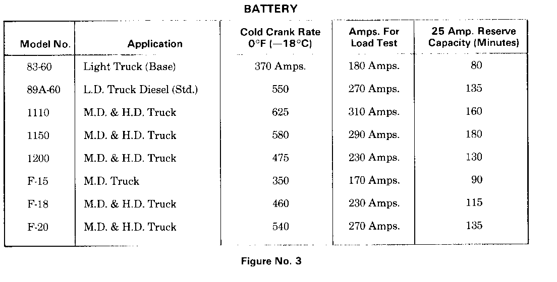
5. It is important to remember that a completely discharged battery must be recharged for a sufficient number of ampere hours (AH) to restore it to a useable state. As a general rule of thumb, using the reserve capacity rating (RC) (refer to Figure No. 3) of the battery as the number of ampere hours of charge will usually bring the green dot into view. For example, if battery is rated at 75 RC minutes, it could be completely recharged as follows:
10 ampere charge x 7-1/2 hours = 75 AH Or 25 ampere charge x 3 hours = 75 AH, etc.
6. It is recommended that any battery recharged by this procedure be LOAD TESTED to establish serviceability.
BATTERY TESTING
Load testing may require use of battery side terminal adapter the same as with charging to ensure good connections. (See Figure No. 2).
1. Connect a voltmeter and a battery load tester across battery terminals.
2. Apply 300 ampere load for 15 seconds to remove surface charge from battery. Remove load.
3. Wait 15 seconds to let battery recover and apply specified load. (Refer to Figure No. 3). Read voltage after 15 seconds with specified load applied, then disconnect load.
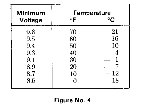
4. Temperature of the battery will change the minimum voltage to pass the load test. To properly determine minimum voltage, estimate temperature battery has been exposed to for the last several hours, i.e. room temperature or outside ambient, to within 10 DEG F. If voltage is equal to or above minimum voltage listed in Figure No. 4, battery is good and should be returned to service. If voltage is less than minimum requirement, replace battery.
JUMP STARTING
Both booster and discharged battery should be treated carefully when using jumper cables. Follow exactly the procedure outlined below, being careful not to cause sparks:
1. CAUTION - Any procedure other than that below could result in: 1) personal injury caused by electrolyte squirting out the battery vent. 2) personal injury or property damage due to battery explosion, 3) damage to the charging system of the booster vehicle or of the immobilized vehicle.
2. Set parking brake and place automatic transmission in "PARK" (neutral for manual transmission). Turn off lights, heater and other electrical loads. Read built-in hydrometer. If indicator is clear or yellow, replace battery. If green dot is visible, failure to start is not due to a discharged battery and the cranking system should be checked. If dark, proceed to Step 3.
3. Take care that the clamps from one cable do not inadvertently touch the clamps on the other cable. Do not lean over the battery when making connections. The ground connection must provide good electrical conductivity and current carrying capacity. Avoid moving, hot or electrical hazards such as fans manifolds and spark plug terminals.
4. Reverse the following cable connection sequence exactly when removing jumper cables. DO NOT PERMIT vehicles to touch each other as this could establish a ground connection and counteract the benefits of this procedure.
5. Attach one end of one jumper cable to the positive terminal of the booster battery and the other end of the same cable to positive terminal of the discharged battery.
6. Attach one end of the remaining cable to the negative terminal of the booster battery and the other end to a ground at least 18 inches from the battery of the vehicle being started. (DO NOT CONNECT DIRECTLY TO THE NEGATIVE POST OF THE DEAD BATTERY.)


General Motors bulletins are intended for use by professional technicians, not a "do-it-yourselfer". They are written to inform those technicians of conditions that may occur on some vehicles, or to provide information that could assist in the proper service of a vehicle. Properly trained technicians have the equipment, tools, safety instructions and know-how to do a job properly and safely. If a condition is described, do not assume that the bulletin applies to your vehicle, or that your vehicle will have that condition. See a General Motors dealer servicing your brand of General Motors vehicle for information on whether your vehicle may benefit from the information.
