SNOW PLOW AUXILIARY LIGHT MAY CAUSE OPEN FUSE

MODEL: 1988-90 C/K 1, 2, 3
Amperage draw due to aftermarket auxiliary lights added when a snow plow is installed on a 1988 through 1990 C/K 1, 2, 3 may exceed the 15 amp capacity of the stop/hazard fuse and cause the fuse to open.
A Service Directional Signal Relay Harness which does not draw current through the stop/hazard/directional switch may be installed to prevent stop/hazard fuse open.
Use the, following instructions to install the Service Directional Signal Relay Harness, P/N 15555168.
Installation Instructions
1. Disconnect battery (batteries).
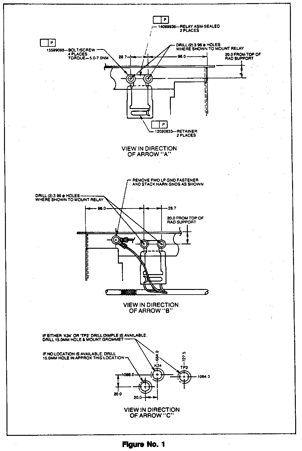
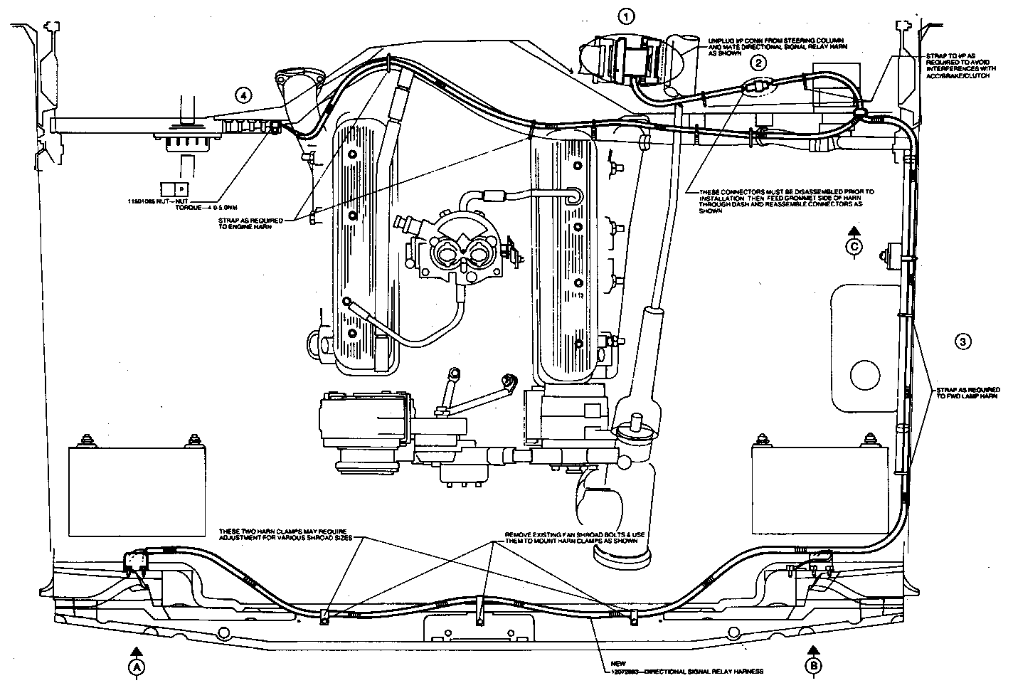
2. See figures 1 and 2 for detail.
3. Drill 15.0 mm hole in cowl (Refer to View in Direction of Arrow C'figure 1) and paint exposed metal surface for corrosion protection.
In Cab
4. Remove access cover from beneath the steering column and disconnect harmonic IP connector (See #1 in layout drawing- figure 2).
5. Remove harmonic connector jumper harness from the directional signal service harness at the two way junction connector (#2 in figure 2).
6. Install service hamess harmonic connectors to existing steering column IP harmonic connections (#1 in figure 2).
7. Feed service harness junction connector through drilled hole. Apply RTV around rubber grommet and seat grommet. Secure harness to IP harness to avoid brake and clutch pedal inference.
8. Connect junction connector (#2 in figure 2).
9. Reinstall access panel cover to steering column.
From the Engine Side
1. Remove battery (batteries) to provide dearance for drilling holes for relay mounting bolts in upper radiator support.
2. Drill holes 20.0 mm down from top of radiator support and 28.7 mm apart. Holes should be 3.96 mm (Refer to View in Direction A and View in Direction B'). Paint exposed metals surfaces for corrosion protection. Attach both left and right relays.
3. Route longer breakout with relay connectors along headlamp wiring as shown (#3 in figure 2) and secure as necessary.
4. Attach service harness to vehicle left relay and ground terminal ring to existing headlamp ground bolt (Refer to 'View in Direction of Arrow B' figure 1).
5. Secure vehicle center section of service harness by removing three fan shroud bolts and using these bolts to secure service harness attaching chps included with part.
6. Attach harness to vehicle right relay (View A).
7. Back at the cowl, attach the branch of the service harness to the engine wiring harness along cowl to the junction block (#4 in figure 2). Secure with ties as necessary.
NOTICE: Take care to provide proper clearance from hot engine parts e.g. exhaust manifolds.
8. Remove junction block cover (#4 in figure 2) and attach ring terminal ring on service harness to the closest stud on the left side (drivers side) with supphed nut. Replace cover.
9. Attach the unused wires at the left and right relays to the aftermarket snow plow directional signal circuits.
10. Reinstall and connect battery (batteries).
PARTS REQUIRED:
1 - Service Directional Signal
Relay Harness 15555168
Parts are currently available from GMSPO.
Use the following Labor Operation and Time:
Labor Operation: T8040 Labor Time: 0.8 Hr.


General Motors bulletins are intended for use by professional technicians, not a "do-it-yourselfer". They are written to inform those technicians of conditions that may occur on some vehicles, or to provide information that could assist in the proper service of a vehicle. Properly trained technicians have the equipment, tools, safety instructions and know-how to do a job properly and safely. If a condition is described, do not assume that the bulletin applies to your vehicle, or that your vehicle will have that condition. See a General Motors dealer servicing your brand of General Motors vehicle for information on whether your vehicle may benefit from the information.
