POWER STG. NOISE WHILE TURNING FREQUENTLY DURING LEFT TURNS

SUBJECT: POWER STEERING SQUAWK WHEN TURNING
MODELS: 1988-91 C/K TRUCKS EQUIPPED WITH POWER STEERING
Some 1988-91 C/K trucks equipped with power steering may experience noise from the power steering gear when turning. This noise is usually described as a squawk and may occur most frequently during left turns.
This condition is caused during machining of the steering valve o-ring groove and o-ring material which was incompatible to the application.
To correct this condition the steering gear valve assembly should be replaced with a new valve assembly that features improved machining and a revised valve spool 0-ring seal (230). The revised seal is black, while the old seal was orange.
VEHICLES INVOLVED
All 1988-1991 C/K trucks equipped with power steering.
SERVICE PROCEDURE:
Tools Required:
J7624 Adjustable Spanner Wrench J4245 Snap Ring Pliers J8524-1 Adjuster Plug Bearing Installer J7079-2 Driver J29810 Seal Protector J7754-01 0-25 lbs. in. torque wrench
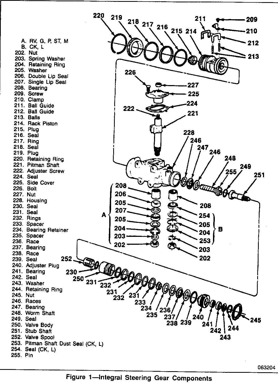
REMOVE (Figure 1)
1. Steering gear from the vehicle. - Refer to section 3Bl of the appropriate C/K service manual for complete removal instructions.
2. Adjuster plug locknut (245).
3. Adjuster plug assembly (240) using J 7624. - Retaining ring (244) using J 4245 or equivalent snap ring pliers. - Washer (243). - Stub shaft oil seal (242). - Adjuster plug seal (239)
4. Steering valve assembly (250) and stub shaft o-ring seal (249).
[!] IMPORTANT It is not necessary to remove the worm shaft (248) and thrust bearing assembly (246, 247) when removing the steering valve assembly. If the worm shaft is removed it will be necessary to remove the rack piston plug (219) to reinstall the worm shaft.
INSTALL (Figure 1)
1. New stub shaft o-ring seal (249).
[!] IMPORTANT The valve body assembly, rings and all seals should be lubricated with power steering fluid before assembly.
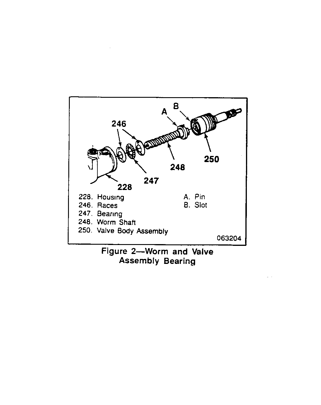
2. New steering valve assembly (250) (Figure 2).
[!] IMPORTANT Note that pin (A) on the worm gear (248) lines up with slot (B) in the steering valve assembly (250).
3. Stub shaft oil seal (242) to adjuster plug (240) using J 8524-1 and J 7079-2. - Be sure adjuster plug bearing (241) is seated in adjuster plug (240). Use J 8524-1 and J 7079-2 if necessary.
4. New adjuster plug seal (239) to the adjuster plug assembly (240).
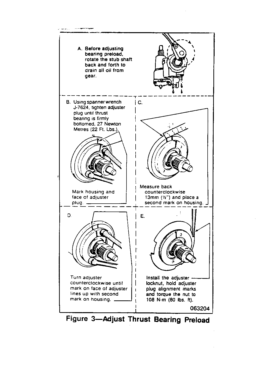
5. Adjuster plug assembly (240) using J 7624. - Place J 29810 over the splined end of stub shaft (251) before installing the adjuster plug (240). This will protect the stub shaft oil seal (242) from damage. - Adjust thrust bearing preload (Figure 3). - After, adjusting thrust bearing preload, check the turning torque of the stub shaft (251) using J 7754-01 (0-25 lbs. in. torque wrench) and a 12-point socket. A torque reading of 5-10 lbs. in. is desired. If this reading is not obtained, repeat the adjustment procedure.
6. Washer (243).
7. Retaining ring (244).
[!] IMPORTANT The retainer projections must not extend beyond the washer (243) when the retaining ring (244) is seated. The washer must be free to rotate.
8. Steering gear to vehicle. - Refer to section 3Bl of the appropriate C/K service manual for complete installation instructions.
SERVICE PARTS INFORMATION
P/N Description Year Applications -------- -------------- ------- ------------ 26010052 Valve Assembly, 1988-91 All Models Steering Gear
26010275 Seal Kit, 1988-91 All Models Adjuster Plug
Parts are currently available from GMSPO.
WARRANTY INFORMATION
For vehicles repaired under warranty use:
Labor Operation Model Labor Time --------------- ----- ----------- T7176 C 1.2 hrs. T7176 K 1.3 hrs.
NOTE: Labor Operation is coded to base vehicle coverage in the warranty system.


General Motors bulletins are intended for use by professional technicians, not a "do-it-yourselfer". They are written to inform those technicians of conditions that may occur on some vehicles, or to provide information that could assist in the proper service of a vehicle. Properly trained technicians have the equipment, tools, safety instructions and know-how to do a job properly and safely. If a condition is described, do not assume that the bulletin applies to your vehicle, or that your vehicle will have that condition. See a General Motors dealer servicing your brand of General Motors vehicle for information on whether your vehicle may benefit from the information.
