BALL JOINT WEAR CHECK INSPECTION-SERVICE PROCEDURES

SUBJECT: C/K TRUCK BALL JOINT WEAR CHECK
MODELS: 1988-1992 C/K TRUCKS
When conducting a routine front suspension check, the following is the correct procedure for determining ball joint wear.
SERVICE PROCEDURE:
Raising the vehicle and moving the front wheel and tire assemblies back and forth or in and out is NOT an acceptable method of checking ball joint wear.
C and K Model Lower:
o Be sure the vehicle rests on a level surface.
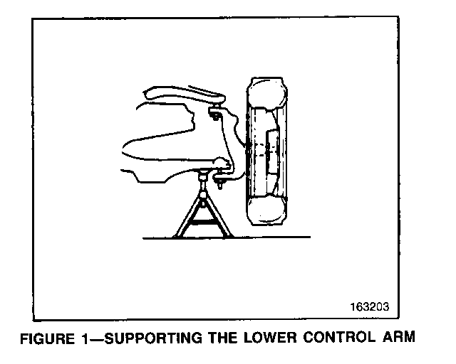
o Raise and support front of vehicle with suitable safety stands. Support the lower control arm with a floor stand or jack as far outboard as possible (Figure 1).
o The vehicle must be stable and should not rock on the floor stands.
o If the vehicle is equipped with aluminum wheels, it may be necessary to first remove the wheel.
To check the ball joints for vertical looseness:
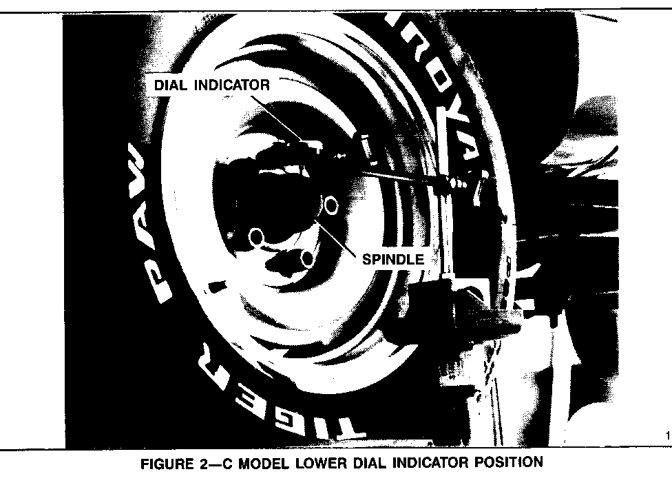
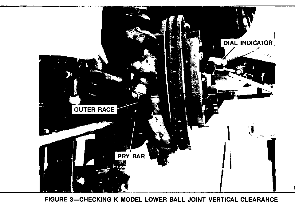
o With the vehicle on the jack stands, place dial indicator against the spindle to show vertical movement (Figures 2 and 3).
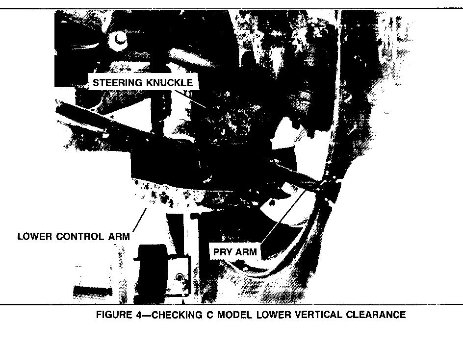
o Pry between the lower control arm and the outer race on K models or between the lower control arm and steering knuckle on C models while reading the dial indicator. This will show vertical looseness in the ball joint (Figures 3 and 4).
o If the dial indicator reading is more than 1 mm (0.040 inch) for a maintenance free ball joint or 2mm (0.080 inch) for a greaseable ball joint, replace the ball joint.
NOTE: Do not pry between the lower control arm and the drive axle seal or in such a manner that the bag joint seal is contacted. Damage to the seal will result.
C and K Model Upper:
o Be sure the vehicle rests on a level surface.
o Raise and support front of vehicle with suitable safety stands. Support the lower control arm with a floor stand or jack as far outboard as possible (Figure 1).
o The vehicle must be stable and should not rock on the floor stands.
o If the vehicle is equipped with aluminum wheels, it may be necessary to first remove the wheel.
To check the ball joints for vertical looseness:
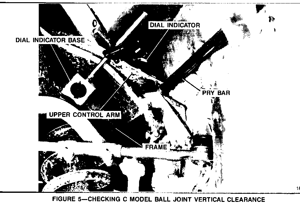
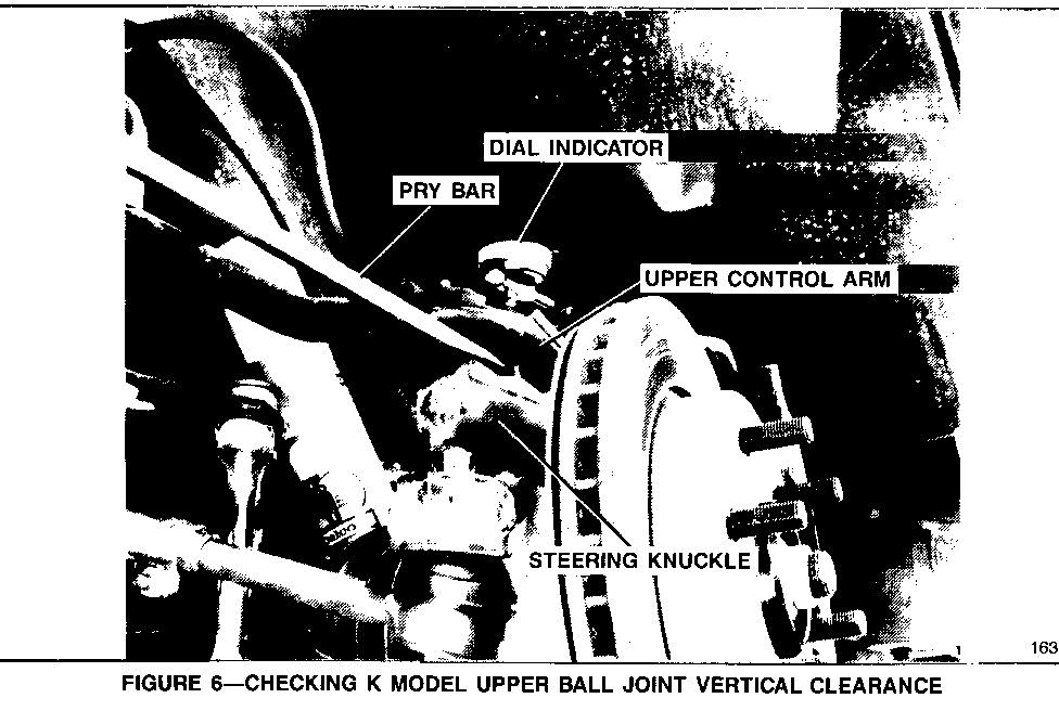
o With front of vehicle supported, position dial indicator with magnetic base on frame and measurement needle on top of the upper ball joint or control arm (Figures 5 and 6).
o With a pry bar, pry between the upper control arm and steering knuckle while observing the dial indicator (Figures 5 and 6). If the reading is more than 1 mm (0.040 inch) for a maintenance free ball joint or 2mm (0.080 inch) for a greaseable ball joint, replace the ball joint.
NOTE: Do not pry in such a manner that the ball joint seal is contacted. Damage to the seal may result.
BALL JOINT WEAR SPECIFICATIONS
Type Wear Specification ---------------- ---------------------------- Maintenance Free 1mm (0.040 inch) vertical Ball Joint movement
Greaseable Ball 2mm (0.080 inch) vertical Joint movement
General Motors bulletins are intended for use by professional technicians, not a "do-it-yourselfer". They are written to inform those technicians of conditions that may occur on some vehicles, or to provide information that could assist in the proper service of a vehicle. Properly trained technicians have the equipment, tools, safety instructions and know-how to do a job properly and safely. If a condition is described, do not assume that the bulletin applies to your vehicle, or that your vehicle will have that condition. See a General Motors dealer servicing your brand of General Motors vehicle for information on whether your vehicle may benefit from the information.
