CENTER CONSOLE LINER DE-BONDS (SERVICE PROC.INSTALL RIVETS)

SUBJECT: CENTER CONSOLE LINER DEBONDS (INSTALL RIVETS)
MODELS: 1992 C/K WITH BUCKET SEATS AND A CENTER CONSOLE
Some owners of 1992 C/K vehicles equipped with bucket seats and a center console may comment that the console liner has become detached from the console compartment. The adhesive bond between the compartment and the compartment liner may debond and allow the liner to become loose and only partially attached. To correct this condition, the console liner may be reattached by using the following riveting procedure.
SERVICE PROCEDURE:
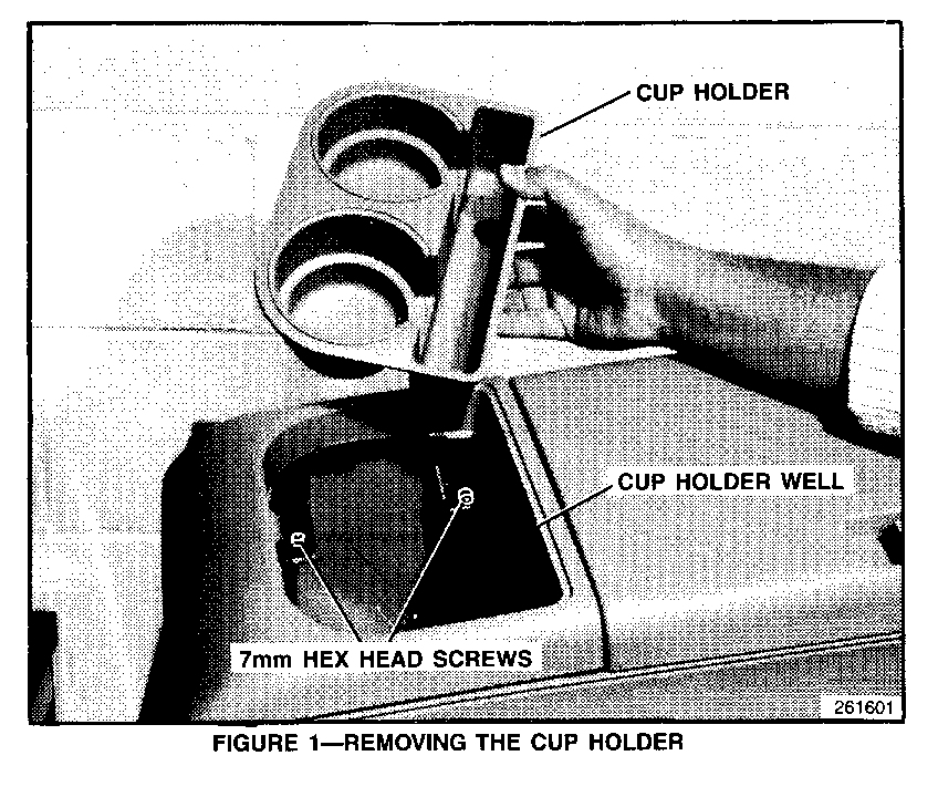
1. Remove the cup holder (figure 1).
2. Remove the four 7-mm hex head screws located in the cup holder well (figure 1).
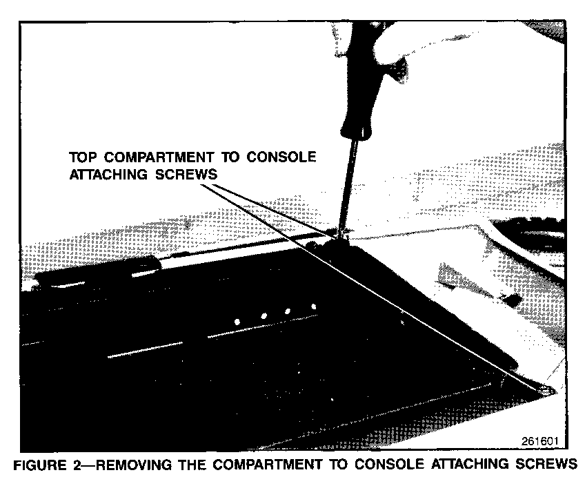
3. Remove the two top compartment-to-console attaching screws (figure 2).
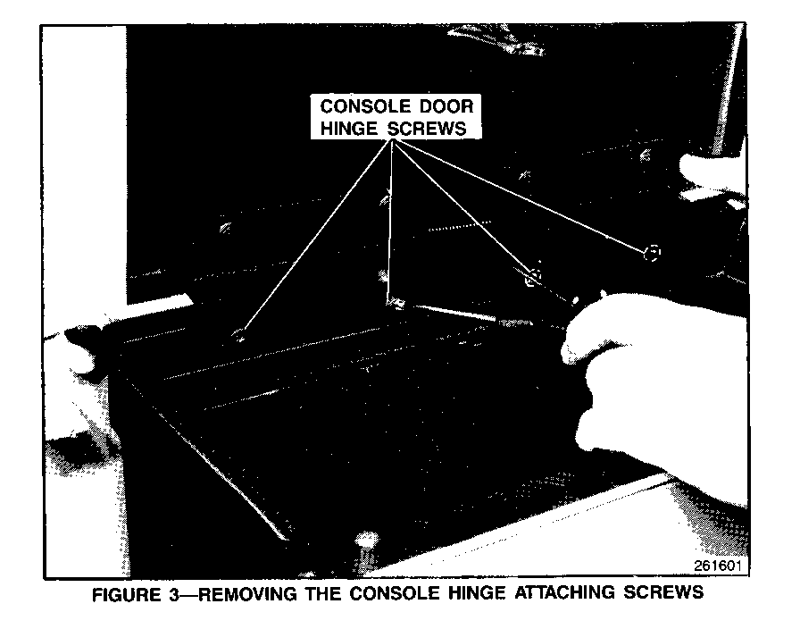
4. Raise the console door and remove the four Phillips head screws from the console door hinge (figure 3).
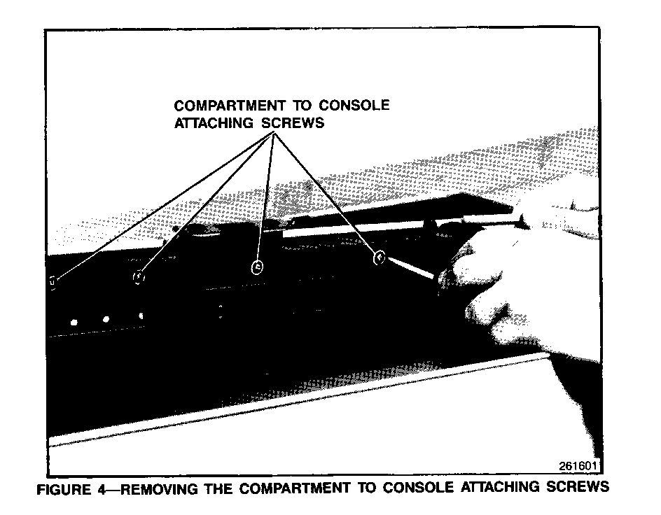
5. Remove the four Phillips head screws from the opposite side of the console. These screws are directly across from the hinge attaching screws (figure 4).
6. The inner compartment may now be removed from the console and taken to a work bench or other suitable work area.
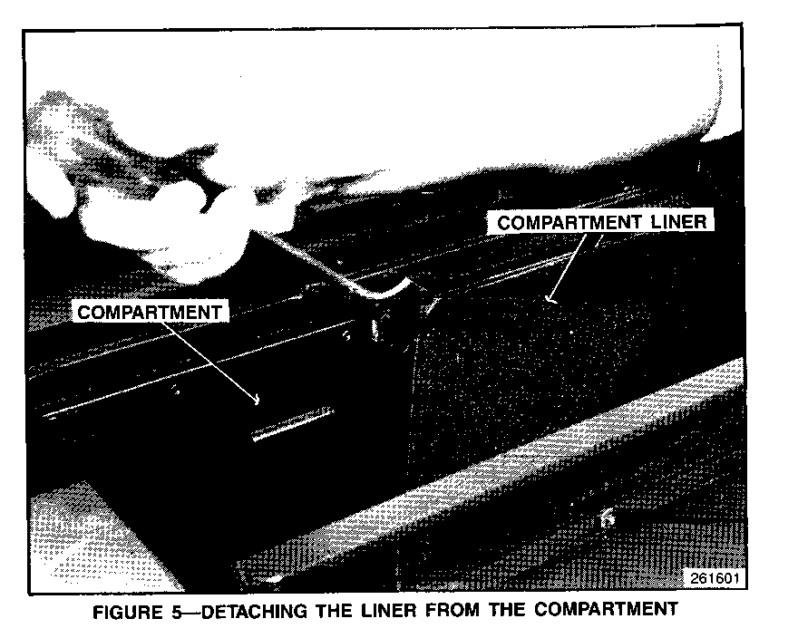
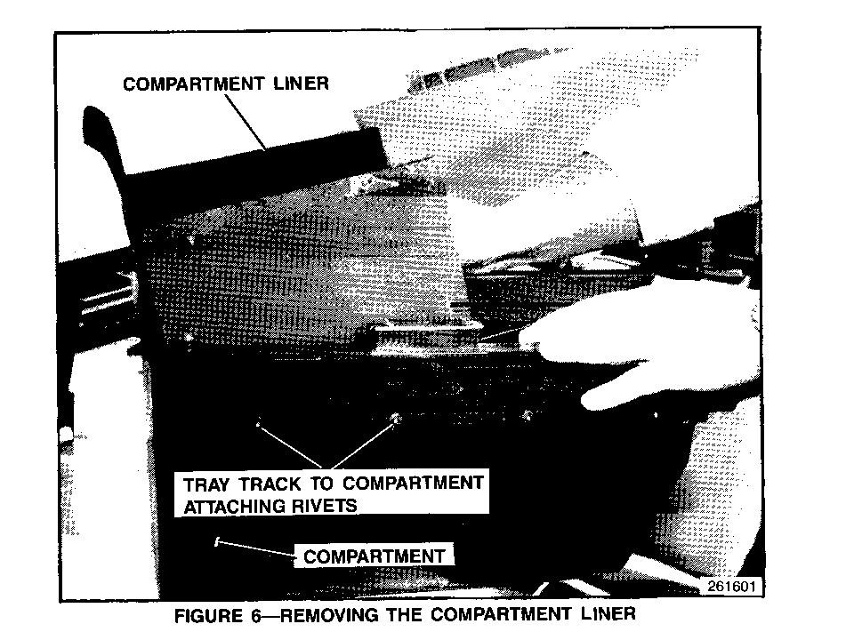
7. Remove the ice bucket and sliding tray. If the liner is loose, remove it. If the liner is only partially loose, carefully detach the rest of the liner with a putty knife, gasket scraper, or similar tool (figures 5 and 6).
8. On either outboard side of the compartment you will see four rivets that attach the sliding tray track to the compartment. Locate the two of these rivets that are at the forward end of the compartment. These rivets are normally under the lining material (figure 6).
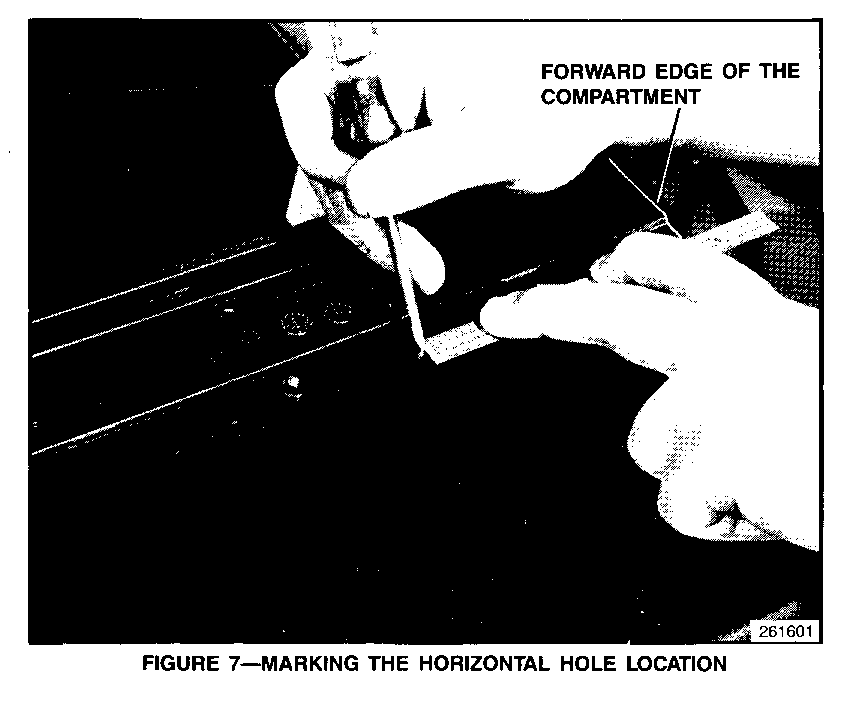
9. Measure and mark a point 4 5/8 inches (113.0 mm) from the forward edge of the compartment. This point should be centered between the two forward rivets (figure 7).
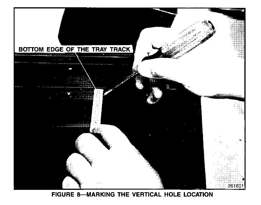
10. At the center point between the two rivets, measure 3/8 inches (9.0 mm) down from the bottom edge of the sliding tray track (figure 8).
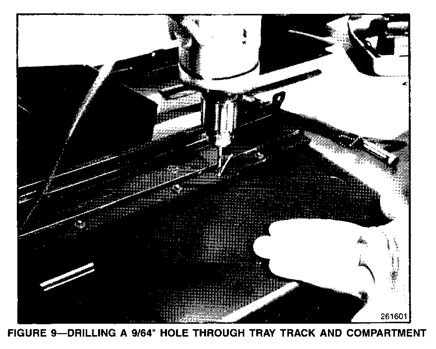
11. At the intersection of the two marks, drill a 9/64-inch (3.0-mm) hole (figure 9) through the tray track and the compartment wall.
12. Repeat steps 9 - 11 on the opposite side of the compartment.
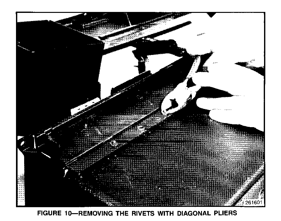
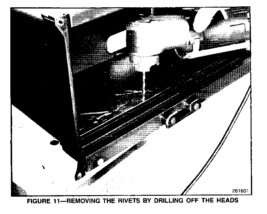
13. Remove the two forward-most rivets on both sides of the compartment by cutting the mushroomed ends with wire-cutting pliers or drilling off the rivet heads using a 11/64-inch (4.0-mm) drill bit and right angle drill (figures 10 and 11).
14. Reinstall the liner making sure that it is pushed solidly against the bottom of the compartment (figure 6). If the liner was damaged, replace it with a new liner (P/N 12540324).
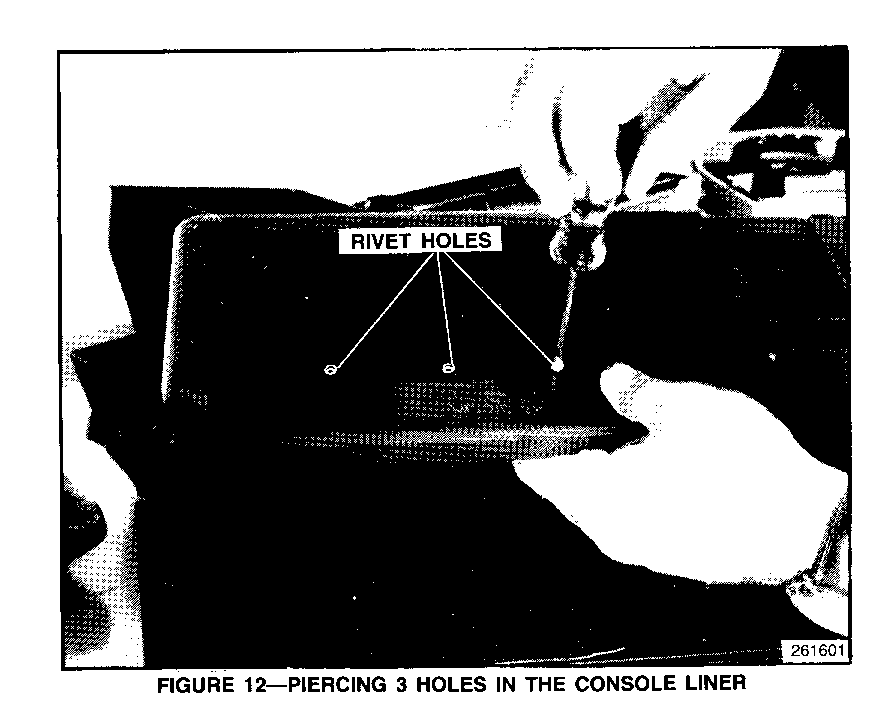
15. With an awl or similar tool, punch a hole through the lining material at each of the two new holes and also the four holes left by removing the rivets (figure 12).
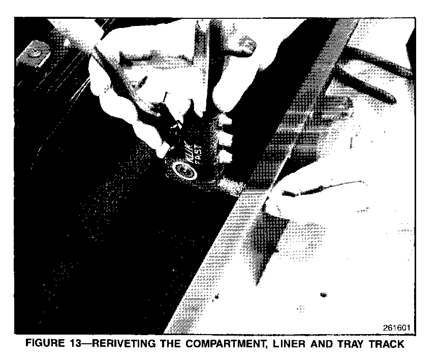
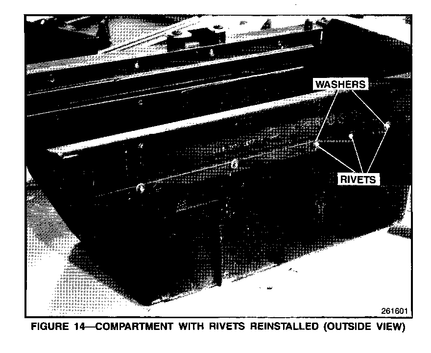
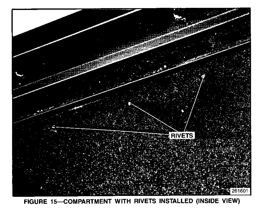
16. Dress the liner around the punched holes as needed. Rivet the liner, compartment, and track together with six 1/8-inch pop rivets. The rivets should be acquired locally. They should be aluminum rivets with a grip length of 0.375-0.50 inches (9.0-12.0 mm) and a black finish.
Important
When installed, the rivet heads should face the inside of the compartment. Place the backing washers back in their original locations. No washer is needed on the additional center rivet (figures 13, 14, and 15).
17. Reassemble the center console by reversing steps 1 - 7.
SERVICE PARTS INFORMATION:
Qty/ Part Number Description Vehicle ----------- ----------- ------- 12540324 Compartment Liner 1 Acquire locally: 1/8" Aluminum Pop Rivets 6
Parts are expected to be available on 3/16/92. in case of limited inventory, parts will be placed on 400 control to waive VIP surcharges. Only verifi- able emergency orders will be accepted. SPO will make every effort to obtain parts. However, the part will be shipped premium transportation at the deal- er's expense and all other order types will be placed on backorder until the 400 control is removed.
WARRANTY INFORMATION:
For vehicles repaired under warranty use:
Labor Operation: T7391 Labor Time: 0.7 hrs.
Note: Labor Operation is coded to base vehicle coverage in the Warranty System.
General Motors bulletins are intended for use by professional technicians, not a "do-it-yourselfer". They are written to inform those technicians of conditions that may occur on some vehicles, or to provide information that could assist in the proper service of a vehicle. Properly trained technicians have the equipment, tools, safety instructions and know-how to do a job properly and safely. If a condition is described, do not assume that the bulletin applies to your vehicle, or that your vehicle will have that condition. See a General Motors dealer servicing your brand of General Motors vehicle for information on whether your vehicle may benefit from the information.
