CAMPAIGN: AUTO TRANS REAR INTERNAL GEAR (REPLACE GEAR)

SUBJECT: 4L80-E OR 4L80-EHD AUTOMATIC TRANSMISSION REAR INTERNAL GEAR
MODELS: 1992 C/K, P30 TRUCKS AND G VANS
General Motors has determined that certain 1992 GMC C/K, P30 Trucks and G Vans equipped with 4L80-E or 4L80-EHD automatic transmissions may have a transmission rear internal gear with an improper heat treat process. With extended use this may cause noisy operation, sluggish forward gear operation, no motion in reverse, and/or no motion in drive. To correct this condition, dealers are to replace the rear internal gear.
VEHICLES INVOLVED
Involved are CERTAIN 1992 C/K, P30 Trucks and G Vans equipped with 4L80-E or 4L80-EHD auto- matic transmission (RPO MT1) and built within the following VIN breakpoints:
Plant Year Model Plant Code From Through ------ ---------- -------- ------ -------- -------- 1992 C/K Pickup Oshawa "1" N1516356 N1545094 1992 C/K Pickup Pontiac "E" NE523244 NE537546 1992 C/K 3500 HD/ Janesville "J" NJ515028 NJ521224 Suburban/ Crew Cab NJ703364 NJ713828 1992 P30 Detroit "3" N3500470 N3501230 1992 G-Van Scarborough "4" N4501904 N4521811
1992 G-Van Lordstown "7" N75082001 N7513747
Vehicle Identification Number Computer Listings are furnished to all involved dealers with the campaign bulletin.
DEALER CAMPAIGN RESPONSIBILITY
All unsold new vehicles in dealers' possession and subject to this campaign MUST be held and inspected/repaired per the service procedure of this campaign bulletin BEFORE owners take possession of these vehicles.
Dealers are to service all vehicles subject to this campaign at no charge to owners, regardless of mileage, age of vehicle, or ownership, from this time forward.
Owners of vehicles recently sold from your new vehicle inventory are to be contacted by the dealer and arrangements made to make the required cor- rection according to instructions contained in this bulletin.
In summary, whenever a vehicle subject to this campaign enters your vehicle inventory, or is in your dealership for service in the future, please take the steps necessary to be sure the campaign correction has been made before selling or releasing the vehicle.
If the name and address of the owner of an involved vehicle was unavailable to GMC Truck Division at the time of campaign initiation, the dealer must determine the owner's name and address from the dealership sales records. Please provide this information directly on the second copy of the listing next to the applicable VIN so that our records may be updated and the appropriate notification mailed to the owner. This second copy should then be submitted to the address listed below in the previously supplied yellow campaign envelopes.
GMC Truck Division General Motors Corporation 101 Union Street Plymouth, Michigan 48170
OWNER NOTIFICATION
Owners will be notified of this campaign on their vehicles by GMC Truck Division (see copy of owner letter included with this bulletin). A listing of owner names and addresses has been furnished to the involved dealers to enable dealers to follow up with owners involved in this campaign. This listing may contain owner names and addresses obtained from State Motor Vehicle Registration records. The use of such motor vehicle registration data for any other purpose is a violation of law in several states. Accordingly, you are urged to limit the use of this listing to this campaign.
SERVICE PROCEDURE
Numbers in parenthesis refer to figures in this bulletin.
Tools
Required: J-21366 Converter Holding Strap J-3289-20 Transmission Holding Fixture Base J-8763-02 Transmission Holding Fixture J-38655 Transmission Holding Fixture Adapter J-37789 Pump Removal Tool J-38868 Gear Unit Assembly Installer/Remover J-23093 Center Support Tool J-24396 Intermediate Clutch Pack Alignment Tool J-38358- A Forward Clutch Assembly Remover & Installer J-23327 Forward Clutch Spring Compressor J-38734 Intermediate Clutch Piston Compressor Adapter J-38735 Center Support Seal installer/Sizer/Pusher
1. Remove transmission from vehicle and install torque converter holding strap J-21366. When removing transmission, follow procedures in appropriate truck service manual.
NOTICE: For Steps 2-40, refer to the section of the 1992 Light Duty Truck Unit Repair Manual regarding 4L80-E or 4L80-EHD transmissions for detailed procedures and illustrations. Also, be certain to inspect components for cracks and other damage during disassembly and reassembly of transmission.
2. Drain fluid from transmission and dispose of properly.
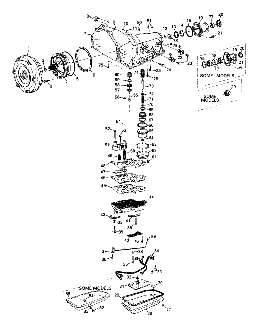
3. Remove two speed sensors (22) and bolts (23) with 8mm socket.
4. Mount transmission on bench fixture using J-3289-20 base, J-8763-02 holding fixture, and J-38655 adapter.
5. Remove converter assembly (1) after removing torque converter holding strap J-21366.
NOTICE: Torque converter is extremely heavy (approximately 65 lbs.), personal injury may result.
6. Remove turbine shaft o-ring (2).
7. For C Trucks or G Vans equipped with transmission models AJP, AFP, MJP, MKP, MLP, MPP, HTP, & TSP remove six 15mm case extension bolts (21), extension assembly (19), extension-to-case seal (15), sleeve output shaft yoke seal (682) and seal output shaft (683).
8. Remove 10mm pan assembly bolts (27), remove pan (28 or 85 depending on model) and seal assembly (29).
NOTICE: Seal assembly (29) will be reused.
9. Remove filter assembly (31) and filter neck seal assembly (32).
10. Disconnect wire harness assembly (34) at pass through connector in the case. NOTICE. Use precautions to protect electrical pins from damage. To prevent electrical connector distress, do not pry off connectors from electrical components.
11. Remove harness assembly with valve assembly complete.
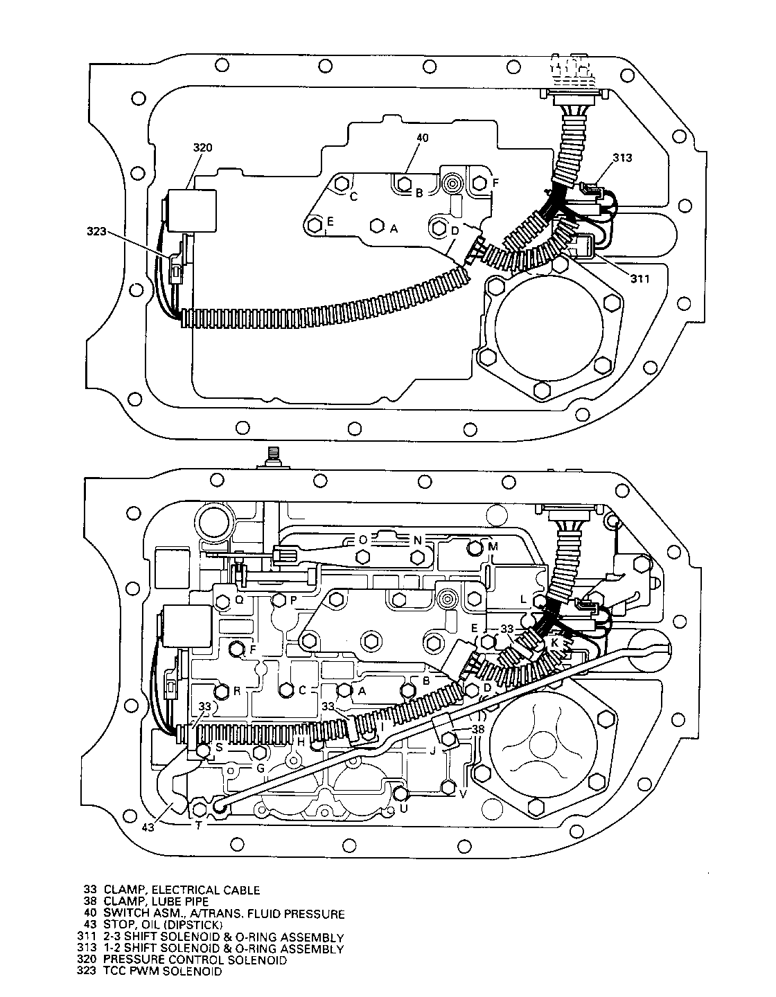
12. Remove 21 valve body assembly bolts (35), manual detent spring and roller assembly (41), lube pipe (39), short lube pipe bolt (36), retainer (37), clamp (38), three wiring clips (33), indicator stop (43), control valve assembly (including accumulator housing) (44), six pressure switch bolts (76), pressure switch assembly (40) and check balls (54).
NOTICE: Do not use a magnet to remove check balls. Magnet could cause a check ball to become magnetized, causing metal particles to stick to check ball.
13. Remove valve-body-to-case gasket (48).
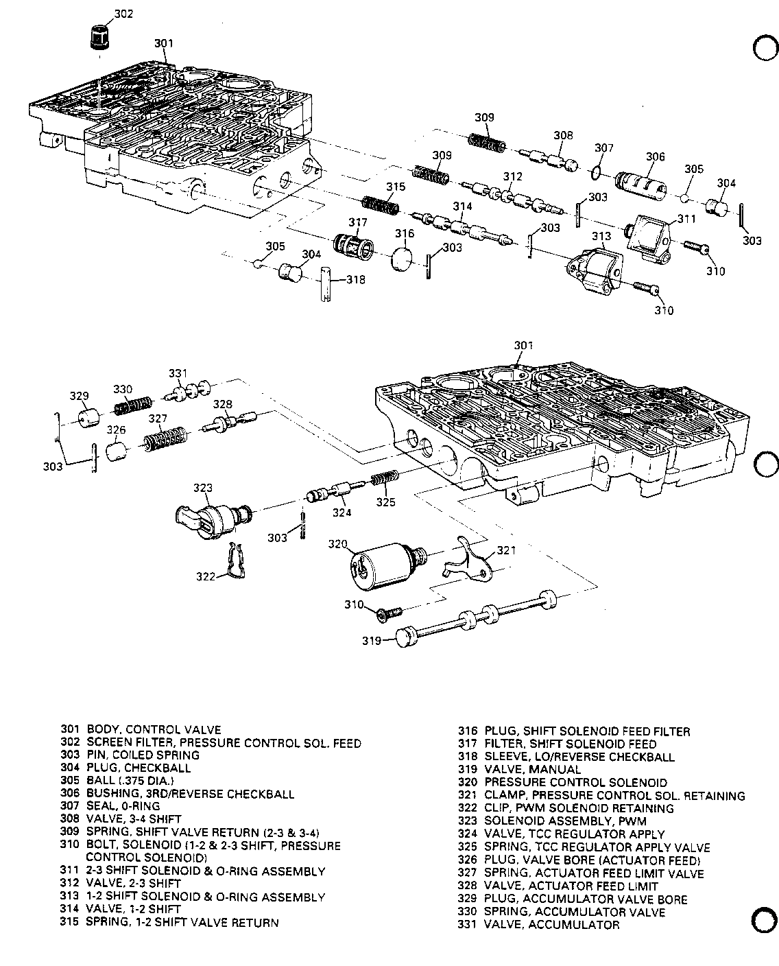
14. Remove manual valve (319) from control valve assembly to prevent damage to manual valve.
15. Remove front servo assembly (55-60).
16. Remove six 10mm rear servo accumulator cover bolts (61), rear servo accumulator cover (62), rear servo accumulator gasket (63) and rear servo accumulator assembly (64-74).
17. Remove 13mm pump assembly bolts (3), pump assembly (4), pump-to-case seal (5) and pump-cover-to-case gasket (6). Use J-37789 when removing pump assembly.
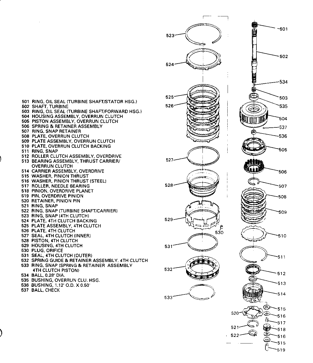
18. Remove complete overdrive unit (501-522).
19. Remove 4th clutch bolt (26) using 40t torx head socket. Bolt will not be reused.
20. Remove housing assembly (529).
21. Remove forward clutch assembly (602) using J-38358-A.
22. Remove thrust washer (612).
23. Remove direct clutch assembly (623) using J-38733.
24. Remove front band (628).
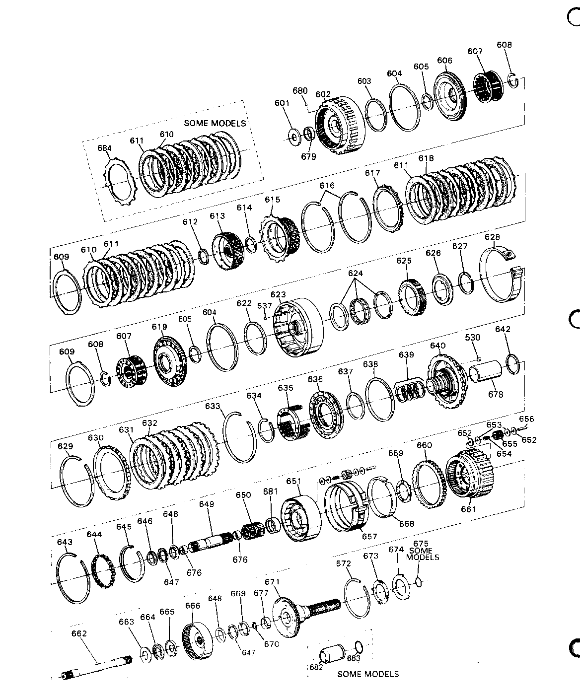
25. Remove snap ring (629), intermediate clutch backing plate (630) and clutch plates (631 & 632).
26. Remove center support bolt (25) using 3/8-12 torx head socket. Bolt will not be reused.
27. Remove snap ring center support (633) and gear unit assembly (634-671) using J-38868.
28. Disassemble gear unit and output assembly (634-671).
29. Install new seal rings (639) to new center support (640) using J-38735. Reuse piston (636), seals (637 & 638), spring & retainer assembly (635), and snap ring (634) using J-23327 and J-38734 and install to center support.
30. Install new rear internal gear (666) to main shaft (662) with snap ring (670).
31. Assemble gear unit and output assembly (634-671).
32. Install gear unit and output assembly (634-671) into case using J-38868 and also installing snap ring (633).
33. Align center support (640) using J-23093.
a. Locate J-23093 into center support direct clutch passage through case.
b. Apply pressure on J-23093, seating center support splines counter- clockwise against case splines (push tool toward rear servo bore).
c. Install new center support bolt (25) using 3/8-12 point torx head socket and torque to 43 N-m (32 lb.ft.). DO NOT OVER TORQUE.
34. Install intermediate clutch plates (632 & 631), backing plate (630) and snap ring (629). Backing plate is to be installed flat side down. Align clutch plates using J-24396.
NOTICE: Dip all clutch plates in Dexron II-E transmission fluid.
35. Install front band (628) and direct clutch assembly (623) using J-38733.
36. Install thrust washer.
37. Install forward clutch assembly (602) into case using J-38358-A.
38. Install 4th clutch assembly (529) into case and install new 4th clutch bolt (26).
39. Disassemble 4th clutch plates (525 & 526), backing plate (524) and snap ring (523) to ease installation of overdrive unit (Step 42).
40. Rotate transmission to horizontal position and torque 4th clutch bolt (26) to 15-17 Nm (11-13 lb. ft.). DO NOT OVER TORQUE.
41. Install complete overdrive unit (501-522) into case.
42. Install 4th clutch plate (525 & 526), backing plate (524) and snap ring (523).
NOTICE: Install steel plates with narrow tang at 'one o'clock' position.
43. Install new pump gasket (6), new pump seal (5) and pump assembly (4) to case (7) with new bolts (3). Torque bolts to 24 Nm (18 lb. ft.) with 13mm socket.
44. Install turbine shaft o-ring (2) to turbine shaft (502).
45. Install front servo assembly (55-60).
46. Install rear servo accumulator spring (74), servo parts (64-73), new rear servo accumulator gasket (63), rear servo accumulator cover (62) and six 10mm rear servo accumulator bolts (61) into case (7). Torque rear servo accumulator bolts to 24 Nm (18 lb. ft.).
47. Install check balls (54) in proper location.
NOTICE: Do not use a magnet to install check balls. Magnet could cause a check ball to become magnetized and cause metal particles to stick to the ball.
48. Install new valve-body-to-case gasket (48).
49. Install manual valve (319) into valve body assembly.
50. Install valve body assembly/accumulator (44) and wiring harness assembly (34) onto case.
51. Make certain that 5 o-rings are attached to switch assembly.
52. Install spring and roller assembly (41) to valve body.
53. Install fluid indicator stop (43), wiring clips (33), lube pipe clamp (38) and lube pipe (39) to valve body. Long end of lube pipe (39) inserts into case (7) and short end inserts into valve body.
54. Install 21 valve body assembly bolts (35) and torque to 11 Nm (97 lb. in.) using a 10mm socket. Be certain to torque bolts (35) in alphabetical sequence shown in illustration attached.
55. Install pressure switch assembly (40) with 6 pressure switch assembly bolts (76). Torque bolts (76) to 11 Nm (97 lb. in.) using a 8mm socket.
Be certain to torque bolts in alphabetical sequence shown in illustration attached.
56. Install lube pipe clip (37) to valve body with short bolt (36) and torque to 11 Nm (97 lb. in.) using 10mm socket.
57. Install wiring harness (34) to five or six connectors (if removed).
58. Install new filter assembly (31), filter neck seal assembly (32), reusable pan seal (29), pan (28 or 85 depending on model), and pan bolts (27). Torque pan bolts to 24 Nm (18 lb. ft.) using 10mm socket.
59. For C Trucks or G Vans with transmission models AJP, AFP, MJP, MKP, MLP, MPP, HTP, or TSP, install new sleeve output shaft yoke seal (682) and new seal output shaft (683) onto output shaft. Also, install extension assembly (19), seal (15) and six bolts (21). Torque bolts to 34 Nm (25 lb. ft.) using 15mm socket.
60. Install two speed sensors, bracket assemblies (22) and two bolts (23). Torque bolts to 11 Nm (97 lb. ft.) using Bmm socket.
61. Install torque converter assembly (1) and install holding strap J-21366.
NOTICE: Torque converter is extremely heavy (approximately 65 lbs.), personal injury may result.
62. Remove transmission from bench fixture and install into vehicle.
63. Disconnect holding strap J-21366.
64. Install transmission into vehicle.
65. Fill transmission to proper level per cold check procedure.
66. Test drive vehicle.
67. Check transmission fluid and fill to proper level when transmission is at proper temperature.
68. Install Campaign Identification Label.
SERVICE PARTS INFORMATION
Parts are to be obtained from General Motors Service Parts Operation (GMSPO). To ensure that these parts will be obtained as soon as possible, they should be ordered from GMSPO on a C.I.O. order with no special instruction code but order under an advise code (2).
Part Number Description Qty/Veh.
8687940 Rear Internal Gear Repair 1 Package (For Trans. Models: BMP, BNP, DPP, DRP, LLP, BYP, BZP)
8687939 Rear Internal Gear Repair 1 Package (For Trans. Models: ABP, ACP, AFP, AJP, BAP, BJP, MBP, MKP, MPP, BSP, BUP, MAP, MJP, MLP, MHP, DCP, DLP, DNP, HTP, TWP, TSP, LAP, LFP)
8683922 Greased Output Shaft Sleeve 1 & Seal Assembly (For C Trucks and G Vans with Trans. Models: AJP, AFP, MJP, MKP, MLP, MPP, HTP, TSP
12345881 Dexron II-E Automatic Trans- 5 quarts mission Fluid
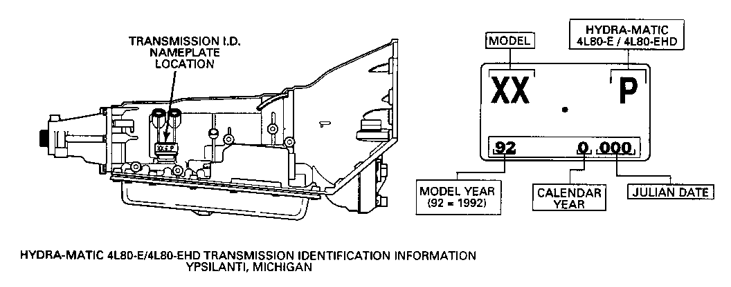
Rear Internal Gear Repair Packages (P/N's 8687940 & 8687939) consist of two layers containing the following (Order only one of these packages per vehicle depending on transmission model type. See illustration attached for location of transmission model code):
1st Layer: Center Support, CenterSupport Bolt, Rear internal Gear, Pump Assembly Bolts, Filter Assembly, Converter Seal Assembly, Fourth Clutch Bolt, Small Package With Oil Fill Tube Multi-Lip Seal, Manual Shift Shaft Seal Assembly and Force Motor Feed Filter Assembly.
2nd Layer: (Under cardboard insert) Center Support Seal Rings, Pump Gasket, Pump Seal, Rear Servo Cover Gasket, and Valve-Body-To-Case Gasket.
NOTICE: The previous center support and rear internal gear must be discarded after the normal warranty retention period. DO NOT REUSE THESE PARTS.
Also, some parts in Kits 8686939 and 8687940 will not be installed as part of the procedures in this bulletin.
WARRANTY INFORMATION
Dealers should submit an accurately filled out Warranty Repair Order on each vehicle completed under this campaign.
Labor Operation *Time Trouble Number Description Allowance Code --------- --------------------- --------- --------- Install Rear Internal Gear
V7490 C-Truck 4.4 hrs. 96 V7492 C-Truck Heavy Duty 4.6 hrs. 96 (12,000#-15,000# GVW) V7493 K-Truck 5.8 hrs. 96 V7495 G-Van 4.1 hrs. 96 V7497 P-Chassis 4.6 hrs. 96
NOTE: Time Allowance includes 0.3 hrs. for test drive
Add: Case extension .2 hrs. sleeve and seal assembly on some C Trucks and G Vans.
With skid plate on .3 hrs some K Trucks
* For dealer to receive Administrative Time Allowance associated with this campaign, add 0.1 hour to the Labor Operation Time Allowance.
CAMPAIGN IDENTIFICATION LABEL
Each vehicle corrected in accordance with the instructions outlined in this product campaign bulletin will require a "Campaign Identification Label". Each label provides a space to include the campaign number and five (5) digit dealer code of the dealer performing the campaign service. This information may be inserted with a typewriter or ball point pen.
Each "Campaign Identification Label" is to be located on the radiator core support in an area which will be visible when the vehicle is brought in for periodic servicing by the owner.
Apply "Campaign Identification Label" only on a clean, dry surface.
ADMINISTRATIVE PROCEDURE
Procedures covering this campaign are outlined in Section V of your dealership's "GM Truck Claims Processing Manual" #P9119.
Dear GMC Truck Owner:
General Motors has determined that certain 1992 GMC C/K, P30 Trucks and G Vans equipped with 4L80-E or 4L80-EHD automatic transmissions may have a transmission rear internal gear with an improper heat treat process. With extended use this may cause noisy operation, sluggish forward gear operation, no motion in reverse, and/or no motion in drive.
To correct this condition, dealers are to replace the rear internal gear. This service will be completed for you at no charge.
Instructions for performing this service have been sent to your GMC Truck dealer. Please contact your dealer to arrange a service date. Ask your dealer if you wish to know how much time will be needed to schedule, process and repair your vehicle.
The enclosed postage paid owner reply card identifies your vehicle. Presenta- tion of this card to your dealer will assist in making the necessary correction to your vehicle in the shortest possible time. If you have sold or traded your vehicle, please furnish us complete name and address of the person you sold or traded your vehicle to and return the card to us.
We are sorry to cause you this inconvenience; however, we have taken this action in the interest of your continued satisfaction with our products.
General Motors bulletins are intended for use by professional technicians, not a "do-it-yourselfer". They are written to inform those technicians of conditions that may occur on some vehicles, or to provide information that could assist in the proper service of a vehicle. Properly trained technicians have the equipment, tools, safety instructions and know-how to do a job properly and safely. If a condition is described, do not assume that the bulletin applies to your vehicle, or that your vehicle will have that condition. See a General Motors dealer servicing your brand of General Motors vehicle for information on whether your vehicle may benefit from the information.
