Removal Procedure
Tools Required
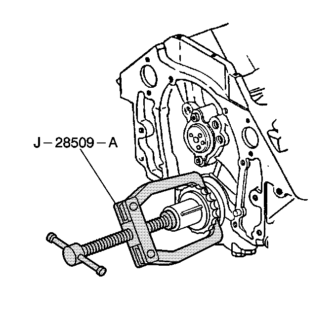
| • | J 28509-A Crankshaft Sprocket Remover |
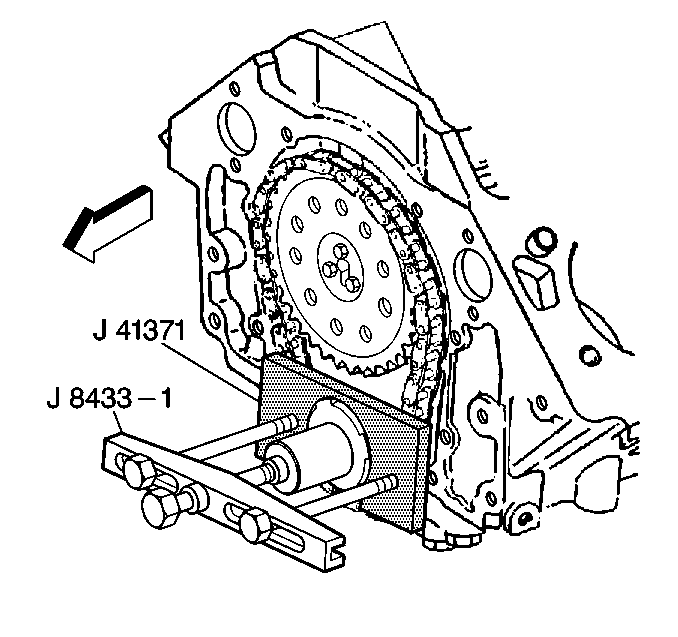
| • | J 41371 Reluctor Wheel Remover |
- Disconnect the battery negative cable from the battery. Refer to Battery Cable in Engine Electrical.
- Remove upper fan shroud from the radiator. Refer to Fan Shroud Replacement in Engine Cooling.
- Rotate the engine until the timing marks on the crankshaft balancer and the engine front cover are on TDC.
- Remove the drive belt from the vehicles drive pulleys. Refer to Drive Belt Replacement .
- Raise the vehicle and support with safety stands. Refer to Lifting and Jacking the Vehicle in General Information.
- Remove the lower fan shroud from the radiator. Refer to Fan Shroud Replacement in Engine Cooling.
- Remove the crankshaft balancer from the crankshaft. Refer to Crankshaft Balancer Replacement .
- Remove the water pump from the engine block. Refer to Water Pump Replacement in Engine Cooling.
- Remove the engine front cover from the engine block. Refer to Engine Front Cover Replacement .
- Aligned the timing marks on the camshaft and crankshaft gears.
- Use the J 41371 to remove the crankshaft reluctor ring from the crankshaft. Refer to Crankshaft Position Sensor Reluctor Ring Replacement .
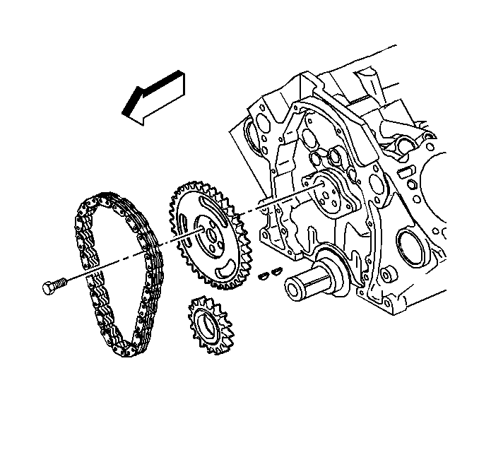
- Remove the camshaft sprocket retaining bolts.
- Remove the timing chain and camshaft sprocket.
- Use the J 28509-A to remove the crankshaft sprocket.
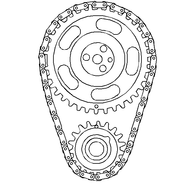
Important: If the crankshaft position reluctor ring is removed, a new crankshaft position reluctor ring sensor must be installed.
Installation Procedure
Tools Required
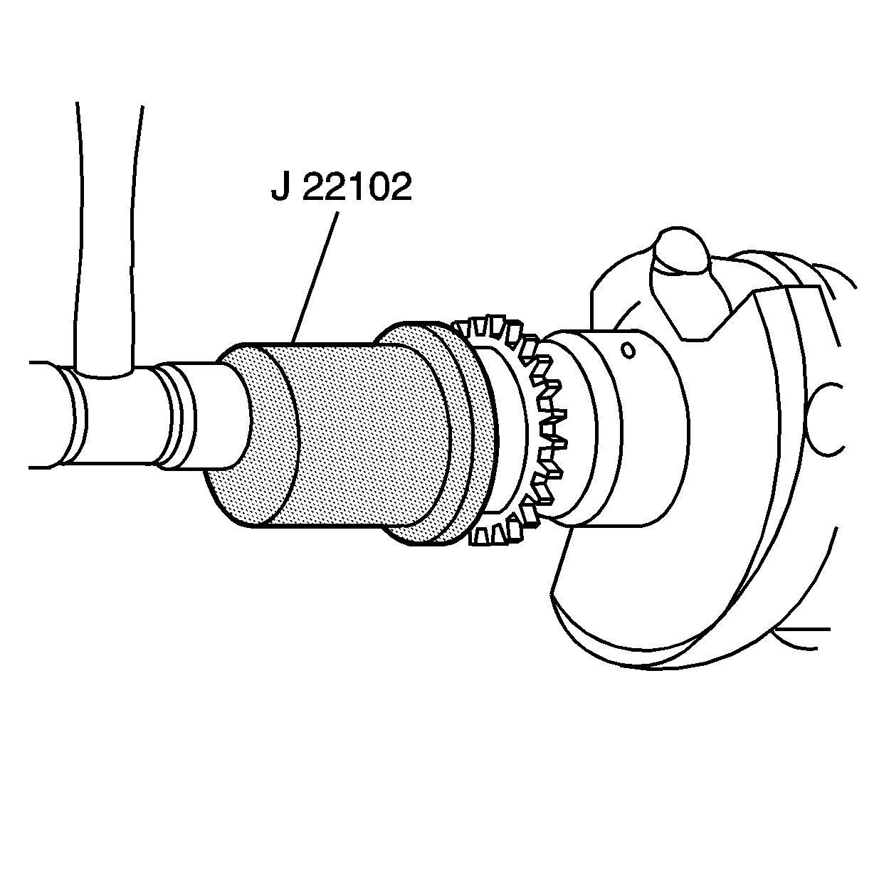
J 22102 Crankshaft Sprocket Installer
- Use the J 22102 to install the crankshaft sprocket.
- Install the timing chain and sprocket to the camshaft.
- Install the camshaft retaining bolts to the camshaft.
- Install the timing chain and sprocket to the camshaft.
- Install the engine front cover to the engine block. Refer to Engine Front Cover Replacement .
- Install a new crankshaft position reluctor ring to the crankshaft. Refer to Crankshaft Position Sensor Reluctor Ring Replacement in Engine Mechanical.
- Install the crankshaft balancer to the crankshaft. Refer to Crankshaft Balancer Replacement .
- Install the water pump to the engine block. Refer to Water Pump Replacement in Engine Cooling.
- Install the lower fan shroud to the radiator. Refer to Fan Shroud Replacement in Engine Cooling.
- Lower the vehicle. Refer to Lifting and Jacking the Vehicle in General Information.
- Install the drive belt on the vehicle drive pulleys. Refer to Drive Belt Replacement .
- Install the upper fan shroud to the radiator. Refer to Fan Shroud Replacement in Engine Cooling.
- Connect the battery negative cable to the battery. Refer to Battery Cable in Engine Electrical.
Important: Ensure the following conditions exist:
• The camshaft and the crankshaft timing marks are aligned • The camshaft dowel pin and the camshaft sprocket holes are properly
aligned • The gears and the chain mesh properly

Notice: Do not hammer the camshaft sprocket onto the camshaft. To do so may dislodge the rear camshaft plug and damage the camshaft.
Notice: Use the correct fastener in the correct location. Replacement fasteners must be the correct part number for that application. Fasteners requiring replacement or fasteners requiring the use of thread locking compound or sealant are identified in the service procedure. Do not use paints, lubricants, or corrosion inhibitors on fasteners or fastener joint surfaces unless specified. These coatings affect fastener torque and joint clamping force and may damage the fastener. Use the correct tightening sequence and specifications when installing fasteners in order to avoid damage to parts and systems.
Tighten
Tighten the retaining bolts to 30 N·m (22 lb ft).

