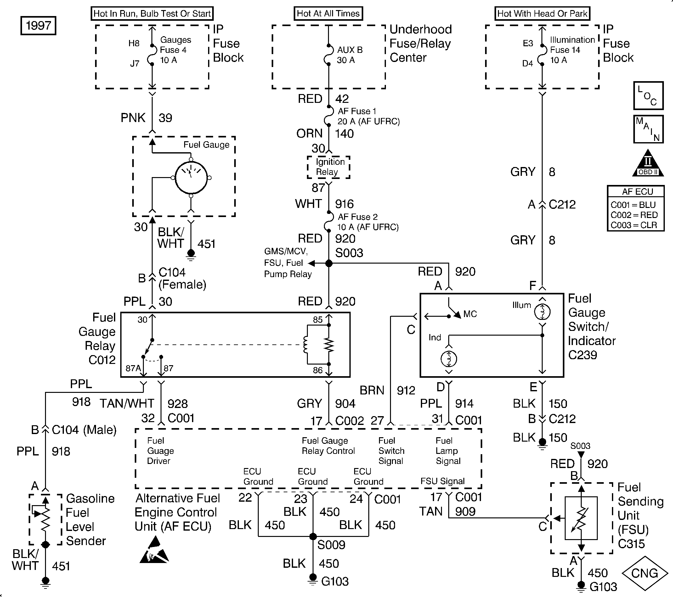
Diagnostic Aids
Important: The gauge will display the dormant fuel level for 10 seconds when the fuel gauge selector switch is pressed. It will then return to normal operation.
Check for the following conditions:
| • | Verify that the CNG fuel tank is at least one-third full (1,200 psi). Add fuel if needed. |
| • | Verify that the High Pressure Lock-off (HPL) connector is connected. |
| • | Verify that the manual lock-down screw in the HPL is open. |
Step | Action | Value(s) | Yes | No |
|---|---|---|---|---|
1 |
Does the fuel gauge read above empty? | -- | Go to Step 23 | Go to Step 2 |
2 |
Important:: This procedure may set a DTC 51 (GMS Frequency Low) in the AF fuel system. Was the HPR pressure within the specified range? | 130-220 psi | Go to Step 3 | Go to Fuel System Diagnosis |
3 |
Does the fuel gauge indicate FULL? | -- | Go to Step 4 | Go to Step 5 |
4 |
Does the DVOM display a voltage within the specified range? | 11-13 V | Go to Step 11 | Go to Step 17 |
5 | Inspect for voltage at CKT 909 (TAN) at terminal C of C315 using a DVOM. Is the voltage within the specified range? | 11-13 V | Go to Step 6 | Go to Step 9 |
6 |
Is the voltage within the specified range? | 6-7 V | Go to Step 7 | Go to Step 10 |
7 | Ground CKT 30 (PPL) at terminal 30 of C012 using a jumper wire. Does the gauge read empty? | -- | Go to Step 23 | Go to Step 8 |
8 | Install a jumper wire between CKT 30 (PPL) at terminal 30 and CKT 918 (PPL) at terminal 87A of C012. Is the action complete? | -- | Go to Instrument Cluster Diagnosis in Instrument Panel, Gauges and Console in the 1997 C/K Truck Service Manual | -- |
9 |
Is there continuity? | -- | Go to Step 13 | Go to Step 21 |
10 |
Is there continuity? | -- | Go to Step 13 | Go to Step 21 |
11 | Inspect for a faulty connection at ECU connector C001. Was a problem found? | -- | Go to Step 21 | Go to Step 12 |
12 | Inspect for continuity of CKT 909 (TAN) at terminal C of C315 to C001, pin 17, using a DVOM. Is there continuity? | -- | Go to Step 14 | Go to Step 21 |
13 | Inspect for a faulty connection at ECU connector C001. Was a problem found? | -- | Go to Step 21 | Go to Step 20 |
14 | Inspect for a faulty connection at FSU connector C315. Was a problem found? | -- | Go to Step 21 | Go to Step 15 |
15 | Inspect for a short to ground on CKT 909 (TAN) at C001, pin 17, using a DVOM. Was a problem found? | -- | Go to Step 21 | Go to Step 16 |
16 | Replace the Fuel Sending Unit (FSU). Refer to Fuel Sender Replacement . Is the repair complete? | -- | Go to Step 23 | -- |
17 |
Does the DVOM display a voltage within the specified range? | 11-13 V | Go to Step 18 | Go to Step 19 |
18 | Repair the open in ground circuit 450 between C315 and G013. Refer to Repair Procedures in Electrical Diagnosis in the 1997 C/K Truck Service Manual. Is the repair complete? | -- | Go to Step 23 | -- |
19 |
Is the action complete? | -- | Go to Step 23 | -- |
20 |
Was a problem found? | -- | Go to Step 21 | Go to Step 22 |
21 | Repair the circuit as necessary. Refer to Repair Procedures in Electrical Diagnosis in the 1997 C/K Truck Service Manual. Is the repair complete? | -- | Go to Step 23 | -- |
22 | Replace the ECU. Refer to Engine Control Unit Replacement . Is the repair complete? | -- | Go to Step 23 | -- |
23 |
Does the fuel gauge read above empty? | -- | Fuel Gauge OK | Go to Step 4 |
