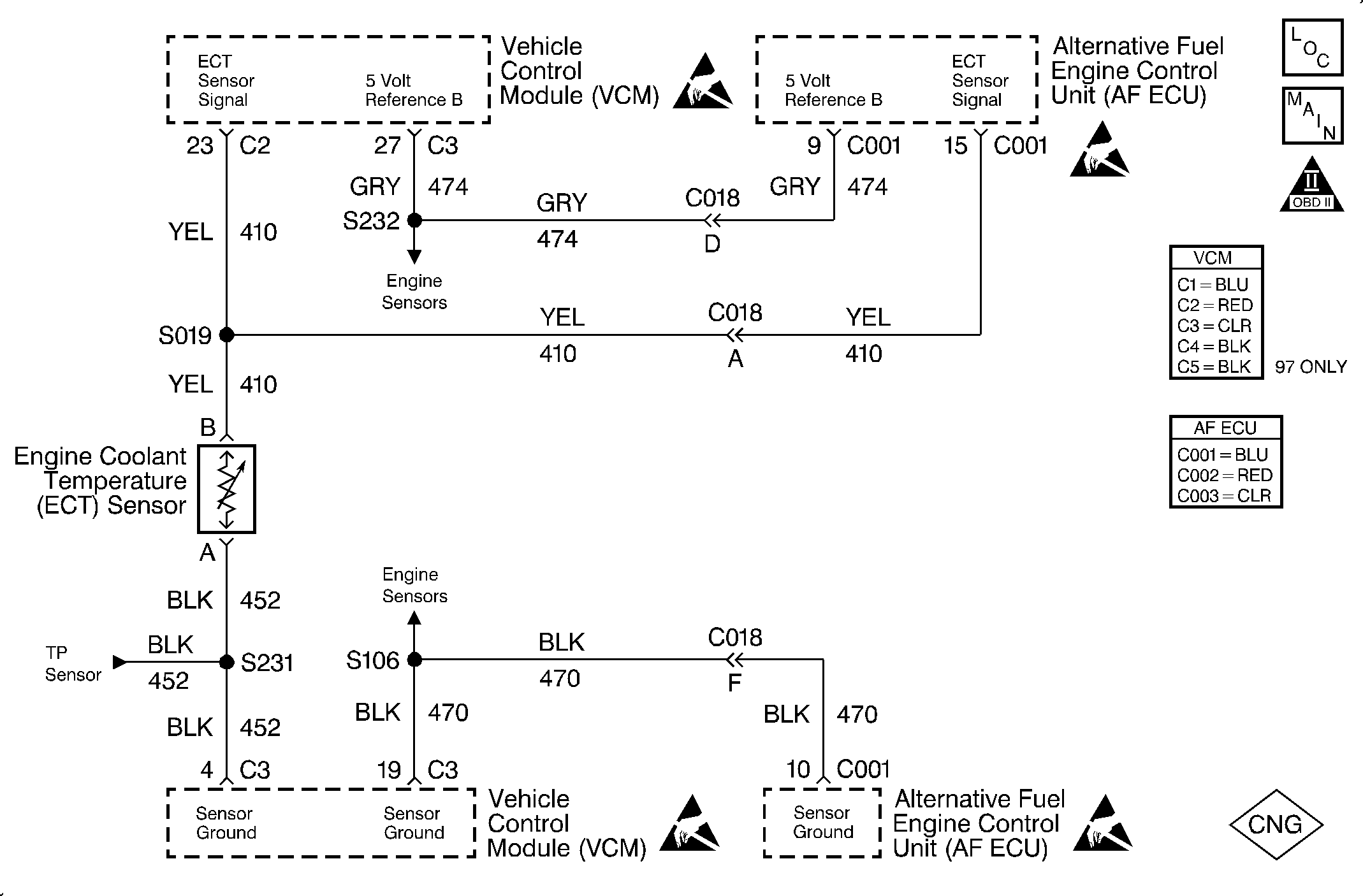
Circuit Description
The Engine Coolant Temperature (ECT) sensor is a thermistor which controls the signal voltage to the VCM. The VCM applies a voltage on the 5 volt reference circuit to the sensor. The sensor resistance is high when the engine is cold. Therefore, the VCM senses a high voltage signal and the VCM indicates a low coolant temperature. The sensor resistance becomes less as the engine warms and the voltage drops indicating high coolant temperature. The voltage measures about 1.5 to 2.0 volts at normal engine operating temperature 85°C to 95°C (185°F to 203°F).
This is a type B DTC.
Conditions for Setting the DTC
The following conditions will set the DTC:
| • | The vehicle is in the CNG operation mode. |
| • | The engine has been running longer than 5 seconds. |
| • | The ECT circuit voltage is less than 0.019 volt. |
Action Taken When the DTC Sets
The ECU sets the DTC 15 after 2 consecutive driving trips with the fault active.
Conditions for Clearing the MIL/DTC
The ECU turns the MIL OFF after 3 consecutive driving trips without a fault condition present. A DTC will clear if no fault conditions have been detected for 40 warm-up cycles (coolant temperature has risen 40°C (72°F) from the start-up coolant temperature and the engine coolant temperature exceeds 70°C (160°F) during that same ignition cycle) or the code clearing procedure has been used.
Diagnostic Aids
Always diagnose ANY VCM codes that are present before beginning this diagnostic procedure.
The temperature should rise steadily to about 90°C (194°F) after starting the engine. The temperature will stabilize when the thermostat opens. A faulty connection or an open in the 5 volt reference circuit or the sensor ground circuit results in a DTC 15.
Use the Temperature vs. Resistance Value Table to test the coolant sensor at various temperature levels in order to evaluate the possibility of a skewed (mis-scaled) sensor. A skewed sensor could result in poor driveability complaints. Refer to Temperature vs. Resistance in Engine Controls - 5.0, 5.7L in the C/K Truck Service Manual.
Test Description
The number(s) below refer to the step number(s) on the diagnostic table.
Step | Action | Value(s) | Yes | No |
|---|---|---|---|---|
1 | Was the Alternative Fuels (AF) Powertrain On-Board Diagnostic (OBD) System Check performed? | -- | Go to Step 2 | Go to Alternative Fuels (AF) Powertrain On Board (OBD) System Check |
2 |
Are the readings close? | -- | Go to Step 3 | Go to Step 4 |
Is the reading on the scan tool and the DVOM below the specified value? | 0.019 V | Go to Step 5 | Go to Step 9 | |
4 |
Is there continuity? | -- | Go to Step 8 | Go to Step 10 |
5 |
Is the voltage less than the specified value? | 0.019 V | Go to Step 6 | Go to Step 8 |
6 |
Is the voltage less than the specified value? | 0.019 V | Go to Step 10 | Go to Step 7 |
7 | Inspect for continuity between the ECU side of C018 and ground using a DVOM. Is there continuity? | -- | Go to Step 10 | Go to Step 9 |
8 | Inspect the ECU connector and pins. Were any problems found? | -- | Go to Step 10 | Go to Step 11 |
9 | The circuit is intermittently failing. Refer to Diagnostic Aids. Was a problem found? | -- | Go to Step 10 | -- |
10 | Repair the faulty or shorted circuit or connection. Refer to Repair Procedures in Electrical Diagnosis in the C/K Truck Service Manual. Is the action complete? | -- | Go to Step 12 | -- |
11 | Replace the ECU. Refer to Engine Control Unit Replacement . Is the action complete? | -- | Go to Step 12 | -- |
12 |
Does the diagnostic run and pass? | -- | Go to Step 13 | Go to Step 2 |
13 | Are any ECU or VCM DTCs displayed that have not been diagnosed? | -- | Go to the applicable DTC table | System OK |
