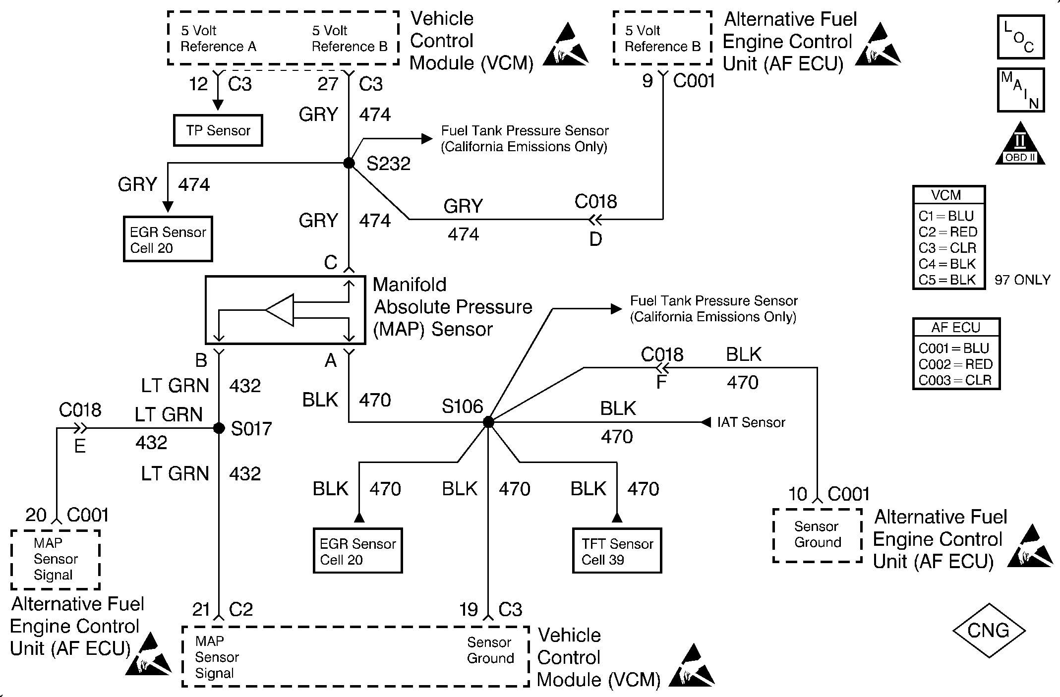
Circuit Description
The Manifold Absolute Pressure (MAP) sensor responds to changes in the intake manifold pressure (vacuum). A 5 volt reference is applied to the sensor. A variable resistor moves in relation to manifold pressure and a voltage signal is sent back to the ECU on the 5 volt reference circuit. This voltage signal varies from 1.0-1.5 volts at closed throttle (high vacuum) to 4.0-4.5 volts at wide open throttle (low vacuum).
A substantial change in throttle position and engine speed must precede any substantial change in MAP. If a substantial change in throttle position and engine speeds has occurred and a change in MAP did not occur, than a MAP malfunction has occurred.
This is a type B DTC.
Conditions for Setting the DTC
The following conditions will set the DTC:
| • | The vehicle is in the CNG operation mode. |
| • | Engine run time is greater than 5 seconds. |
| • | None of the following DTCs are active: 14, 15, 16, 21, 22, 23, 25, 26, 33, 34, 35, 36, 37, 41, 42, 43, 44, 45, 51, 52, 53, 54, 55, 56, 58, 62, 63, 64, 65. |
| • | The TP sensor position is less than 70%. |
A fault is detected if a TP sensor change of greater than 20% is detected while at the same time the corresponding MAP change is less than 6 kPa (1.77 in. mercury).
Action Taken When the DTC Sets
The ECU sets the DTC 32 after 2 consecutive driving trips with the fault active.
Conditions for Clearing the MIL/DTC
The ECU turns the MIL OFF after 3 consecutive driving trips without a fault condition present. A DTC will clear if no fault conditions have been detected for 40 warm-up cycles (coolant temperature has risen 40°C (72°F) from the start-up coolant temperature and the engine coolant temperature exceeds 70°C (160°F) during that same ignition cycle) or the code clearing procedure has been used.
Diagnostic Aids
Always diagnose ANY VCM codes that are present before beginning this diagnostic procedure.
Check the MAP sensor vacuum source for leaks, restrictions or faulty connections.
Check the MAP sensor output voltage to the ECU. This voltage represents a barometric reading to the ECU when the engine is not running.
Test Description
The number(s) below refer to the step number(s) on the diagnostic table.
Important: When comparing the readings from a known good vehicle, compare vehicles which use a MAP sensor having the same color insert or the same Hot Stamped number.
-
Applying 34 kPa (10 Hg) of vacuum to the MAP sensor should cause the voltage to change. The voltage value obtained from subtracting the second reading from the first should be greater than 1.5 volts. When applying vacuum to the sensor, the change should be instantaneous. A slow voltage change indicates a faulty sensor.
Important: The electrical connector must remain securely fastened.
Important: Replace the MAP sensor-to-intake manifold seal after removing the MAP sensor from the intake manifold.
-
Disconnect the sensor from the bracket. Gently twist the sensor in order to check for intermittent connections. Output changes greater than 0.1 volt indicate a bad connector or connection. If the connector is OK, replace the sensor.
Step | Action | Value(s) | Yes | No |
|---|---|---|---|---|
1 | Was the Alternative Fuels (AF) Powertrain On-Board Diagnostic (OBD) System Check performed? | -- | Go to Step 2 | Go to Alternative Fuels (AF) Powertrain On Board (OBD) System Check |
2 |
Is the MAP sensor voltage within the typical scan tool data, plus or minus the specified value? | 0.4 V | Go to Step 3 | Go to Step 7 |
3 |
Are the readings close? | -- | Go to Step 4 | Go to Step 6 |
Is the difference greater than the specified value? | 1.5 V | Go to Diagnostic Aids | Go to Step 5 | |
Check the MAP sensor connections. Was a problem found? | -- | Go to Step 6 | Go to Step 7 | |
6 | Repair the circuit as necessary. Refer to Repair Procedures in Electrical Diagnosis in the C/K Truck Service Manual. Is the action complete? | -- | Go to Step 8 | -- |
7 | Replace the MAP sensor. Refer to MAP Sensor Replacement in Engine Controls - 5.0, 5.7L in the C/K Truck Service Manual. Is the action complete? | -- | Go to Step 8 | -- |
8 |
Does the diagnostic run and pass? | -- | Go to Step 9 | Go to Step 2 |
9 | Are any ECU or VCM DTCs displayed that have not been diagnosed? | -- | Go to the applicable DTC table | System OK |
