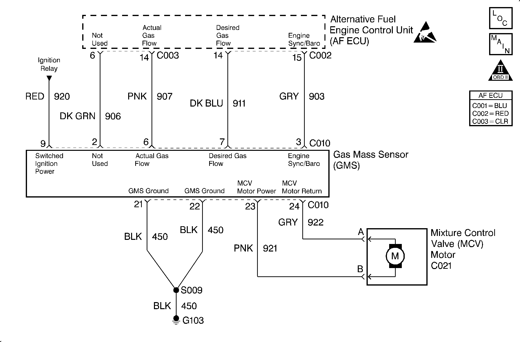
Circuit Description
The Gas Mass Sensor (GMS) provides a frequency signal proportional to the mass-flow of gaseous fuel entering the engine. The GMS actual gas signal varies from about 700 Hz at idle to about 2700 Hz at Wide Open Throttle (WOT).
The GMS desired gas signal from the ECU is an input to the GMS which is a frequency ranging from about 700 Hz to 5000 Hz. This signal, when present, activates the GMS and commands a desired Mixture Control Valve (MCV) position.
The GMS actual gas signal is one of the most important inputs used by the ECU for fuel control while operating on CNG. The GMS provides fuel mass-flow feedback to the ECU which is used to precisely trim the position of the MCV for the required fuel flow rate.
This is a type A DTC.
Conditions for Setting the DTC
The following conditions will set the DTC:
| • | If the engine speed is between 25 and 500 RPM: |
| - | The battery voltage is greater than 8 volts. |
| - | The GMS frequency output is greater than 2900 Hz for 0.5 second. |
| • | If the engine speed is greater than 500 RPM: |
| - | The battery voltage is greater than 10 volts. |
| - | The engine run time is greater than 10 seconds. |
| - | The GMS frequency output is greater than 2900 Hz for 0.5 second. |
Action Taken When the DTC Sets
The ECU will set DTC 52 and illuminate the MIL lamp after one fault has occurred if a low frequency failure is detected. The ECU will simultaneously initiate a fuel mode switch-over to gasoline. The vehicle will not attempt to operate on CNG again until the next key cycle.
Conditions for Clearing the MIL/DTC
The ECU turns the MIL OFF after 3 consecutive driving trips without a fault condition present. A DTC will clear if no fault conditions have been detected for 40 warm-up cycles (coolant temperature has risen 40°C (72°F) from the start-up coolant temperature and the engine coolant temperature exceeds 70°C (160°F) during that same ignition cycle) or the code clearing procedure has been used.
Diagnostic Aids
Always diagnose ANY VCM codes that are present before beginning this diagnostic procedure.
| • | Incorrect fuel pressure. Pressure that is too high can cause a DTC 52 to set. |
| • | Improper routing of the harness near the secondary ignition system components or wires. |
| • | Inspect the harness for the following conditions: |
| - | Backed out terminals |
| - | Improper mating |
| - | Broken locks |
| - | Improperly formed or damaged terminals |
| - | Poor terminal to wire connection |
| - | A damaged harness |
Important: The GMS mass-flow and commanded flow frequencies cannot be monitored in the gasoline mode at any time. These frequencies cannot be monitored in the CNG mode with the Key On/Engine Off. The signals will only be present while operating on CNG and only with the engine in the crank or run modes.
Test Description
The number(s) below refer to the step number(s) on the diagnostic table.
-
This step verifies the correct system fuel pressures.
-
This step verifies the GMS system voltage connection.
-
This step verifies the GMS ground connections
-
This step inspects for improper routing of the wire harness.
Step | Action | Value(s) | Yes | No |
|---|---|---|---|---|
1 | Was the Alternative Fuels (AF) Powertrain On-Board Diagnostic (OBD) System Check performed? | -- | Go to Step 2 | Go to Alternative Fuels (AF) Powertrain On Board (OBD) System Check |
2 |
Does the DTC set and the MIL illuminate? | -- | Go to Step 3 | Refer to Diagnostic Aids |
Is the voltage within the specified range? | 11-13 V | Go to Step 4 | Go to Step 6 | |
Is there continuity? | -- | Go to Step 5 | Go to Step 6 | |
Was a problem found and repaired? | -- | Go to Step 8 | Go to Step 7 | |
Repair the harness as necessary. Refer to Repair Procedures in Electrical Diagnosis in the C/K Truck Service Manual. Is the repair complete? | -- | Go to Step 8 | -- | |
7 | Replace the GMS/MCV. Refer to Gas Mass Sensor/Mixture Control Valve and Mounting Bracket Replacement . Is the action complete? | -- | Go to Step 8 | -- |
8 |
Does the diagnostic run and pass? | -- | Go to Step 3 | Go to Step 9 |
9 | Are any DTCs displayed that have not been diagnosed? | -- | Go to the applicable DTC table | System OK |
