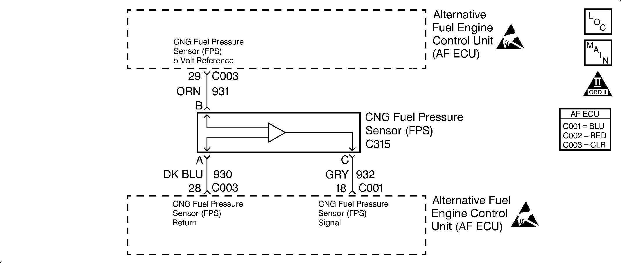
Circuit Description
The fuel pressure sensor (FPS) supplies the ECU with a variable voltage signal from 0.5 volts to 4.5 volts that changes relative to fuel pressure. The FPS voltage varies from about 0.5 volts at 0 kPa (0 psi) to 4.1 volts at 24 820 kPa (3,600 psi). This is a type A DTC.
Conditions for Setting the DTC
The following conditions will set the DTC:
| • | The ignition is ON. |
| • | The FPS voltage is less than 0.25 volt. |
Action Taken When the DTC Sets
The ECU will set DTC 67 and illuminate the MIL after one fault has occurred.
Conditions for Clearing the MIL/DTC
The ECU turns the MIL OFF after three consecutive driving trips without a fault condition present. A DTC will clear if no fault conditions have been detected for 40 warm-up cycles (coolant temperature has risen 40°C (72°F) from the start-up coolant temperature, and the coolant temperature exceeds 70°C (160°F) during that same ignition cycle, or the code clearing procedure has been used.
Diagnostic Aids
When a DTC 67 sets, a short to ground in the FPS circuit is indicated. Always inspect any circuitry that is suspected of causing an intermittent complaint for the following conditions:
| • | Backed out terminals |
| • | Improper mating |
| • | Broken locks |
| • | Improperly formed or damaged terminals |
| • | A poor terminal-to-wire connection |
| • | A damaged harness |
Important: The fuel gauge will display the dormant fuel level for 10 seconds and then return to normal operation when the fuel gauge selector switch is depressed.
Test Description
The number(s) below refer to the step number(s) on the diagnostic table.
-
This step verifies that the fault is present.
-
This step inspects the sensor reference voltage.
-
This step inspects the sensor ground circuit.
Step | Action | Value(s) | Yes | No | ||||||
|---|---|---|---|---|---|---|---|---|---|---|
1 | Was the Alternative Fuels (AF) Powertrain On-Board Diagnostic (OBD) System Check performed? | -- | Go to Step 2 | Go to Alternative Fuels (AF) Powertrain On Board (OBD) System Check | ||||||
Was DTC 67 retrieved? | -- | Go to Step 3 | Go to Intermittent Conditions | |||||||
Backprobe the fuel pressure sensor (FPS) signal circuit in ECU (blue) connector C001 using a DVOM. Is the voltage below the specified value? | 0.25 V | Go to Step 4 | Go to Step 11 | |||||||
4 |
Is the voltage within the specified range? | 4.8-5.2 V | Go to Step 5 | Go to Step 6 | ||||||
Inspect the FPS ground circuit in cavity A for continuity to ground. Is there continuity? | -- | Go to Step 7 | Go to Step 9 | |||||||
6 |
Is a problem found? | -- | Go to Step 13 | Go to Step 11 | ||||||
7 |
Is there continuity? | -- | Go to Step 13 | Go to Step 8 | ||||||
8 | Inspect the FPS signal circuit for continuity between C001 and C315 using a DVOM. Is there continuity? | -- | Go to Step 10 | Go to Step 13 | ||||||
9 |
Is there continuity? | -- | Go to Step 10 | Go to Step 13 | ||||||
10 | Replace the fuel pressure sensor. Refer to Fuel Pressure Sensor Replacement . Is the action complete? | -- | Go to Step 14 | -- | ||||||
11 |
Is a problem found? | -- | Go to Step 13 | Go to Step 12 | ||||||
12 | Replace the engine control unit. Refer to Engine Control Unit Replacement . Is the action complete? | -- | Go to Step 14 | -- | ||||||
13 | Repair the circuit as necessary. Refer to Repair Procedures in Electrical Diagnosis in the 1998 C/K Truck Service Manual. Is the action compete? | -- | Go to Step 14 | -- | ||||||
14 |
Are any other DTCs displayed that have not been diagnosed? | -- | Go to the applicable DTC table | System OK |
