Caution: Do not smoke when installing, maintaining, testing, or troubleshooting
the ether injection system. Make sure you are in a well-ventilated area away
from heat, open flames, or sparks. Wear goggles when testing to avoid eye
injury. Make sure that openings in the valve, tube, or nozzle are pointed
away from you while testing. The starting fluid is extremely flammable and
toxic. It can be harmful or fatal if swallowed.
The following conditions are the most common causes that
prevent starting fluid from reaching the intake manifold:
| • | The ether capsule is empty. |
| • | The metering orifice is clogged. |
Ether Capsule

Perform the following procedure in order to verify
that the ether capsule is not empty:
- Remove the ether capsule from the vehicle.
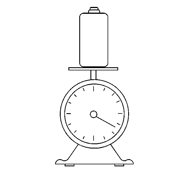
- Weigh the ether capsule.
- Compare the actual weight of the ether capsule against the following
specifications:
| • | An empty ether capsule weighs 440 grams (16 oz). |
| • | A full ether capsule should contain 570 grams (21 oz)
of either and weighs 1020 grams (37 oz) total. |
- If the capsule is empty, replace the empty ether capsule with
a full ether capsule.
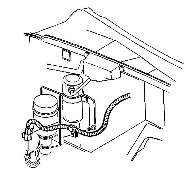
Ether Injector Control Valve

- Inspect for power to the ether injector control valve.
- Inspect the condition of the electrical system.
- If the engine temperature is not low enough for the ETS switch
to close, use a jumper wire in order to complete the circuit will bypass the
switch.
- Remove the ether capsule.
- Crank the engine briefly.
The control valve plunger should move up and remain raised when the
starter is engaged.
- Perform the following actions if the control valve plunger did
not function:
| 6.1. | Disconnect the control valve electrical connector. |
| 6.2. | Momentarily touch the leads across the battery terminals. |
If the control valve does not activate when connected across the battery,
the valve is faulty.
| 6.3. | Replace the control valve if the valve is faulty. |
Refer to Engine Controls for detailed electrical diagnosis.
Engine Temperature Sensor
Tools Required
J 39200 Digital Multimeter
The ETS mounts at the rear of the engine. The ETS is designed to close
when the engine temperature is between -8°C to -1°C (17°F-29°F).
As the temperature rises, the switch will open between 1°C-6°C
(33°F-43°F). The switch may normally be open or closed between
8°C to 6°C (18°F-42°F), depending on engine temperature.
Notice: Do not attempt to check the ETS switch by shorting it across
the battery terminals. Excess current will burn out the switch and it will
have to be replaced.
- Use the J 39200
in order to test the ETS switch for continuity. The ETS must be thoroughly
chilled for at least 10 minutes to a temperature below -8°C (17°F).
Replace the ETS if no continuity exists.
- If continuity exists, warm the switch for at least 10 minutes
to temperatures above 6°C (43°F). Use the J 39200
in order to test again for continuity.
The switch should be open but the J 39200
should not display OL.
- Replace the ETS if the switch fails either test.
Flow Metering Orifice Fitting
A serviceable, filtered, metering orifice controls fluid flow rate.
The metering orifice is located inside the valve fitting connector at the
bottom of the ether injector control valve assembly. Perform the following
procedure in order to inspect for clogging of the fitting:
- Remove the injector nozzles from the engine.
- Crank the engine.
Important: Be sure to spray the fluid into an appropriate container.
- Verify that fluid sprays from the nozzles.
- Perform the following actions if fluid does not spray from the
nozzles:
| 4.1. | Disconnect the tubing from the valve fitting. |
| 4.3. | Verify that fluid sprays from the nozzles. |
- If starting fluid now sprays from the valve fitting when the system
activates, inspect the following components:
| • | Inspect the tubing for the following conditions: |
| • | Inspect the injector nozzles for clogging. |
Important: The fitting end that is installed in the ether injector control valve
has left handed threads.
- If starting fluid does not spray from the valve fitting, remove the
valve fitting from the ether injector control valve for cleaning.
- Remove the filter and the O-ring. Use the following procedure
in order to clean the filter and the fitting:
| 7.1. | Wash the filter and the fitting in a clean solvent. |
Do not allow the solvent to contact the O-ring.
| 7.2. | Use compressed air in order to dry the filter and the fitting. |
| 7.3. | Replace the filter if the filter's condition is still questionable. |
Notice: Do not flush the valve more than twice or the internal seals in the
valve may be damaged.
- Reinstall the O-ring and the filter into the fitting.
Before reinstalling the fitting into the control valve, the valve can
be flushed by activating the system. Be sure to spray the starting fluid into
an appropriate container.
Notice: Do not make any alignment adjustments to the injector nozzles without
referring to the Caterpillar® 3116 Unit Repair Manual. Ether must not
be sprayed where it will contact the air intake heater element.
This could result in an explosion and/or fire, causing immediate engine damage.
- Reinstall the injector nozzles.
The nozzles are directional. The tips should point parallel to the crankshaft.
The nozzle has an external mark in order to indicate the proper orientation.


