Cranking Circuit Resistance Test
Tools Required
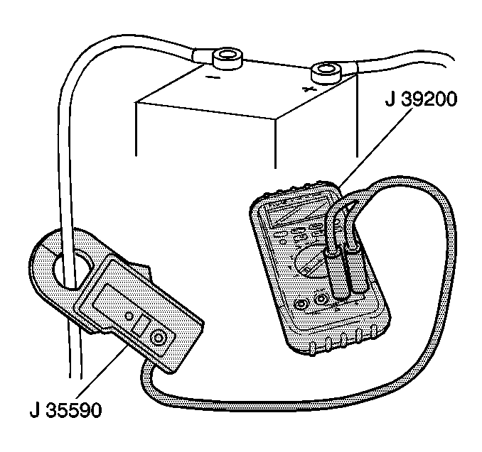
| • | J 39200 J 39200 Digital Multimeter |
| • | J 35590 J 35590 Inductive
Current Clamp |
Perform the following actions in order to prevent the engine from starting
when performing the following tests:
| • | Disconnect the ignition and tachometer harness from the distributor
on gasoline engines. |
| • | Disconnect the fuel shut off solenoid connector on diesel engines. |
The starter motor cannot be measured against specifications while on
the vehicle. Perform a test inspecting for excessive resistance in the starting
circuit.
Allow the vehicle to remain at room temperature before performing the
following tests. Colder weather causes higher resistance in the circuit.
On diesel engine vehicles, disable the following components prior to
performing the circuit test:
| • | The air intake heater on the 6.6L engine |
| • | The glow plug system on the 6.5L engine |
The following test will not be valid if the preheater systems are not
disabled:
Notice: Do not operate the starter motor continuously for more than 30 seconds
without pausing to allow it to cool at least 2 minutes. Overheating from excessive
cranking will seriously damage the starting motor.
- Disable the following components,
as equipped, on diesel engine vehicles:
| • | The air intake heater system. |
| • | Refer to Air Intake Heater in Engine Controls. |
| • | Refer to Glow Plug System in Engine Controls. |
- Verify that the battery is fully charged.
Perform the following steps if the battery has been recently charged:
| • | Remove the surface charge. |
- Connect the J 39200
across
the battery in order to read the open circuit voltage.
The open circuit voltage should measure at least 12 volts.
- Perform the following steps in order to inspect for excessive
resistance in the cranking circuit:
| 4.1. | Connect the J 39200
J 39200
across the negative battery post and the positive terminal of the starter
solenoid. |
| 4.3. | Observe the voltage reading on the J 39200
J 39200 . |
Excessive resistance exists in the cranking circuit if the J 39200
J 39200 reads 2 volts or more when cranking.
| 4.4. | Inspect the cranking circuit for the following conditions: |
| 4.5. | Connect the J 39200
J 39200
across the battery in order to measure the voltage reading in areas where
the J 39200
J 39200 will not reach from
the battery to the starter. |
- Perform the following steps in order to inspect for excessive
resistance in the starter ground circuit:

| 5.1. | Connect one end of the J 39200
J 39200 to the negative battery cable. |

| 5.2. | Connect the other end of the J 39200
J 39200 to the ground stud on the engine block near
the starter motor. |
| 5.4. | Observe the voltage reading on the J 39200
J 39200 . |
The J 39200
J 39200 should read
about 0.2 volt or less when cranking. If the reading is 0.5 volt or higher,
excessive resistance exists in the starter ground circuit.
- Perform the following steps in order to inspect the resistance
of the power supply (B+).
| 6.1. | Connect the J 39200
J 39200
to the positive terminal of the battery and to the positive terminal of the
starter solenoid. |
| 6.3. | Observe the voltage reading on the J 39200
J 39200 . |
Excessive resistance in the starter power supply (B+) exists
if the J 39200
J 39200 reads 0.9 volt
or higher when cranking.
Remove the starter motor for repair if the following conditions exist:
| • | The battery is fully charged. |
| • | The cranking circuit cables and connections are in proper condition. |
| • | Excessive resistance exists in the cranking circuit. |
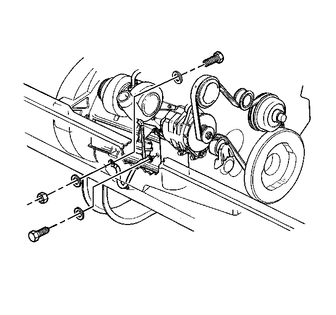
Service the PG-260 starter motor as an assembly replacement.
Thermostat Test
Tools Required
J 39200 Digital Multimeter

The 37-MT/350 starter motor that operates on
the diesel engine is equipped with thermostat for overcrank protection. If
the starter will not crank, use the following procedure in order to inspect
for an open thermostat:
- Ensure that the motor is cool when the circuit should be closed.
The thermostat opens when the thermostat senses starter temperatures
exceeding 140°C (285°F).
- Disconnect the wiring from the thermostat connector.
- Connect the J 39200
to the
two terminals on the thermostat.
- Observe the resistance reading on the J 39200
.
The resistance should measure zero ohms.
- If the J 39200
does not read
zero ohms, replace the thermostat.


