Distributor Overhaul 6.0L/7.0L
Disassembly Procedure
Notice: The ignition system distributor driven gear and rotor may be installed
in multiple positions. In order to avoid mistakes, mark the distributor on
the following components in order to ensure the same mounting position upon
reassembly:
| • | The distributor driven gear |
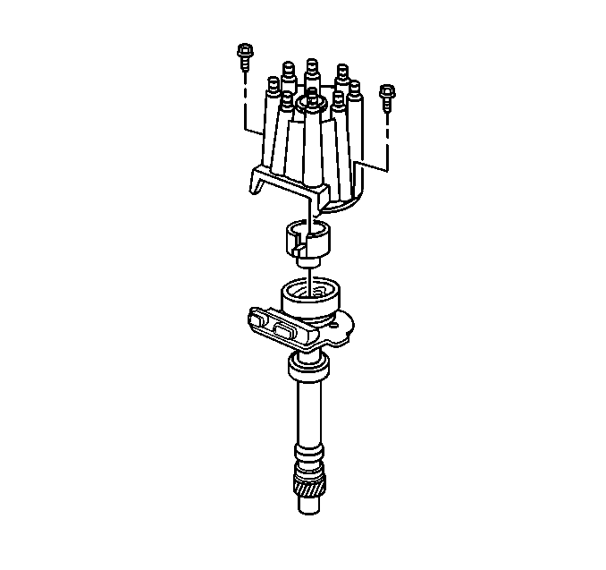
- Remove the two screws
that hold the distributor cap to the distributor housing.
- Remove the distributor cap from the distributor housing.
- Remove rotor from the shaft by lifting straight up.
- Mark the distributor shaft, and distributor drive gear for reassembly.
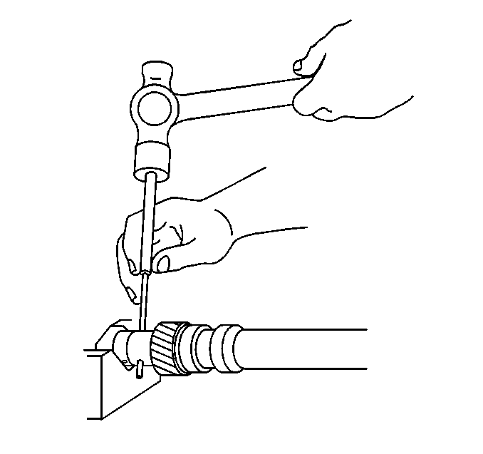
- Support the distributor
drive gear in a V-block or similar fixture.
- Drive out the distributor drive gear roll pin with a suitable
punch.
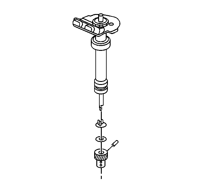
- Remove the driven gear,
round washer, and the tang washer from the distributor shaft.
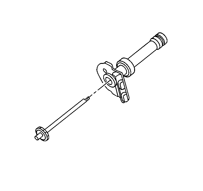
- Remove the distributor
shaft from the distributor housing. If the shaft cannot be removed from the
distributor housing due to varnish buildup, follow these steps.
| • | Remove any burrs from around the roll pin hole in the shaft. |
| • | Secure the distributor housing in a vise, with the gear end down. |
| • | Use a cloth dampened with varnish remover to clean the shaft. |
| • | Do not allow the varnish remover to travel up the distributor
shaft. This may remove the lubrication from the grease pack area. |
| • | Use a twisting motion to pull the shaft out of the housing. |
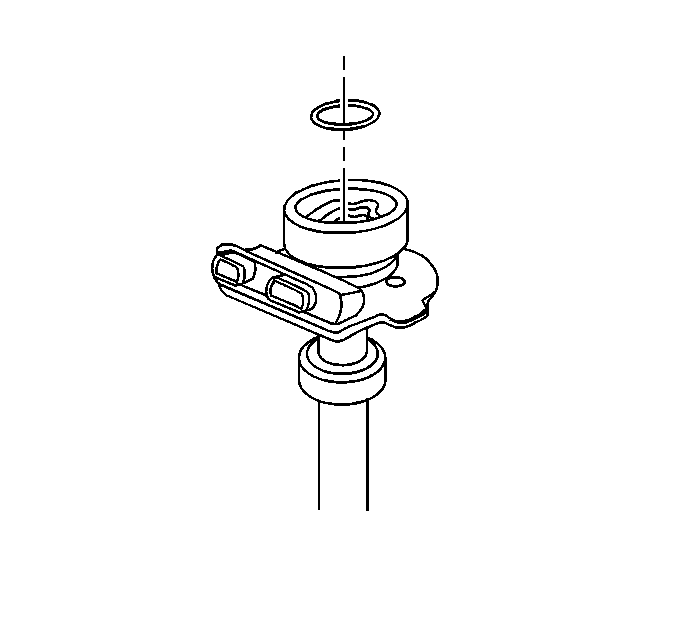
- Remove the distributor
shield lock retainer ring and discard. A new retainer will be needed during
assembly.
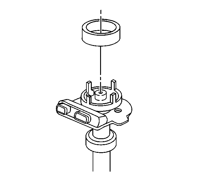
- Remove the distributor
pickup coil shield.
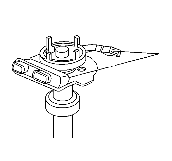
- Disconnect the distributor
pickup coil wiring connector from the ignition control module.
- Remove the distributor pickup coil.
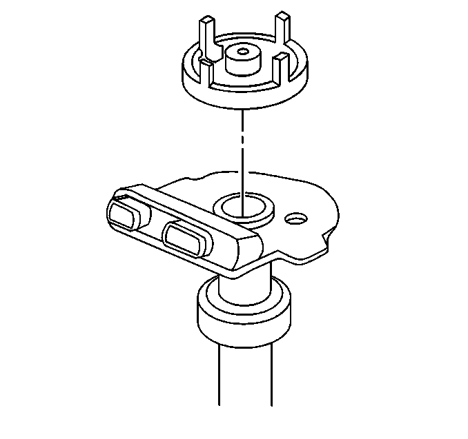
- Remove the distributor
pole piece pickup using a bearing puller.
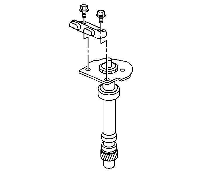
- Remove the two screws
that hold the ignition control module to the distributor housing.
- Remove the ignition control module from the distributor housing.
Inspection Procedure
Tools Required
J 24642-F Module
Tester
- Inspect the distributor cap for cracks or tiny holes. Replace
the cap if it is worn or damaged. Also, inspect the cap for signs of carbon
tracking. Replace the cap if carbon tracking is present.
- Inspect the terminals in the distributor cap for corrosion. Scrape
them clean with a knife or if the corrosion is severe replace the cap. Make
sure the rotor brush, (in the cap), has freedom of movement and no
excessive wear. If the brush is stuck, worn or broken, replace the
cap.
- Inspect the rotor terminal segment for wear or burning. If the
terminal segment appears corroded or burned, replace the rotor. Inspect for
excess amount of carbon dust inside the rotor cup. If carbon dust is
excessive, replace the rotor.
- The rotor should fit snugly on top of the shaft. If not, replace
the rotor.
- Inspect the timer core on the shaft for cracks or damage.
- Inspect the teeth of the stationary pole piece for wear. Wear
would indicate that the timer core teeth have been hitting the stationary
pole piece.
- Inspect the shaft for shaft to bearing looseness. Insert the shaft
in the housing. If the shaft wobbles, replace the housing and/or shaft.
- Make sure the baseplate is tight on the stem of the housing.
- Inspect the housing for cracks or damage.
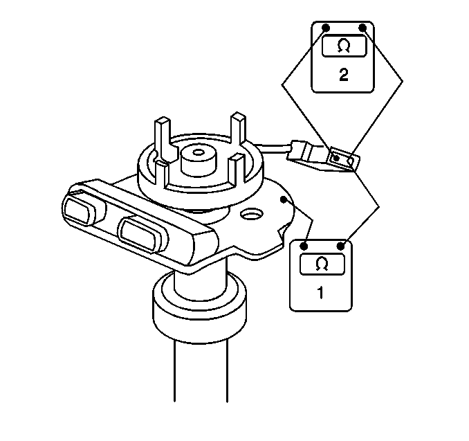
- Measure the resistance
of the pickup coil with a Digital Multimeter, (DMM).
| 10.1. | Connect a DMM to either pickup coil lead and the housing, (1)
The reading should show an open circuit. If not, replace the pickup coil. |
| 10.2. | Connect a DMM to both pickup coil leads, (2). Flex the pickup
coil leads by hand at the coil and the connector to locate any intermittent
opens. The DMM should read a constant value in the 500 to 1500 ohm
range. If not, replace the pickup coil. |
- Check the electrical performance of the module. The module can
only be checked with an approved module tester, such as the J 24642-F
. Follow the tester directions
precisely.
Assembly Procedure

- Coat the bottom of the
ignition control module and mounting area on the housing with silicone dieletric
grease GM P/N 1974984 or equivalent.
- Install the ignition control module to the distributor housing.
Notice: Use the correct fastener in the correct location. Replacement fasteners
must be the correct part number for that application. Fasteners requiring
replacement or fasteners requiring the use of thread locking compound or sealant
are identified in the service procedure. Do not use paints, lubricants, or
corrosion inhibitors on fasteners or fastener joint surfaces unless specified.
These coatings affect fastener torque and joint clamping force and may damage
the fastener. Use the correct tightening sequence and specifications when
installing fasteners in order to avoid damage to parts and systems.
- Install the two
screws that hold the ignition control module to the distributor housing.
Tighten
Tighten the screws to 1.7 N·m (15 lb in).

- Install the distributor
pole piece pick-up.

- Install the distributor
pickup coil.
- Install the distributor pickup coil wiring connector to the module.

- Install the distributor
shield onto the coil.

- Install a new lock retainer
ring to the distributor
shield.

- Lubricate the distributor
shaft, and lower housing
bearing with a few drops of engine oil.
- Install the distributor shaft into the distributor housing.

- Install the tang washer.
- Install the round washer.
- Install the driven gear onto the distributor shaft.
- Line up the marks on distributor shaft, distributor drive gear.

- Support the distributor
drive gear in
a V-block or similar fixture.
- Drive the distributor drive gear roll pin in with a suitable
punch.

- Install the distributor
rotor onto the
distributor shaft.
- Install the distributor cap onto the distributor housing.
- Install the two screws that hold the distributor cap to the distributor
housing.
Tighten
Tighten the screws to 1.7 N·m (15 lb in).


