Charging System Operation 21-SI 200 Series Generators

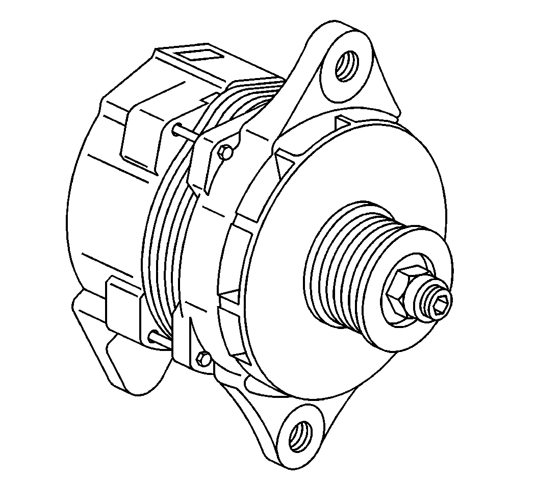
The 21-SI 200 Generators are Systems Integral series generators. The Systems Integral series generators are equipped with a built-in regulator.
The solid state regulator and brush holder assembly attaches to the slip ring end frame. The regulator voltage setting cannot be adjusted.
The regulator is equipped with the following two terminals:
| • | The R (Relay) terminal |
| • | The I (Indicator) terminal |
The R terminal operates auxiliary equipment in some circuits such as the tachometer. The I terminal feeds an indicator lamp or gauge.
The rotor bearings contain enough grease in order to eliminate the need for periodic lubrication. Two brushes perform the following actions:
| • | Carry current through slip rings to the field coil mounted on the rotor. |
| • | Provide long periods of attention-free service (under normal conditions). |
The stator windings are assembled on the inside of a laminated core that forms part of the generator frame. A rectifier bridge connected to the stator windings contains six diodes. The rectifier bridge electrically converts the stator AC voltages to a DC voltage at the generator output BAT terminal. A diode trio that connects to the stator windings supplies the generator field current. A capacitor or condenser that mounts in the end frame performs the following actions:
- Protects the rectifier bridge and diode trio from high voltages.
- Suppresses radio noise.
No periodic maintenance or adjustment is required on the generator assembly.
Charging System Operation CS-Series Generators
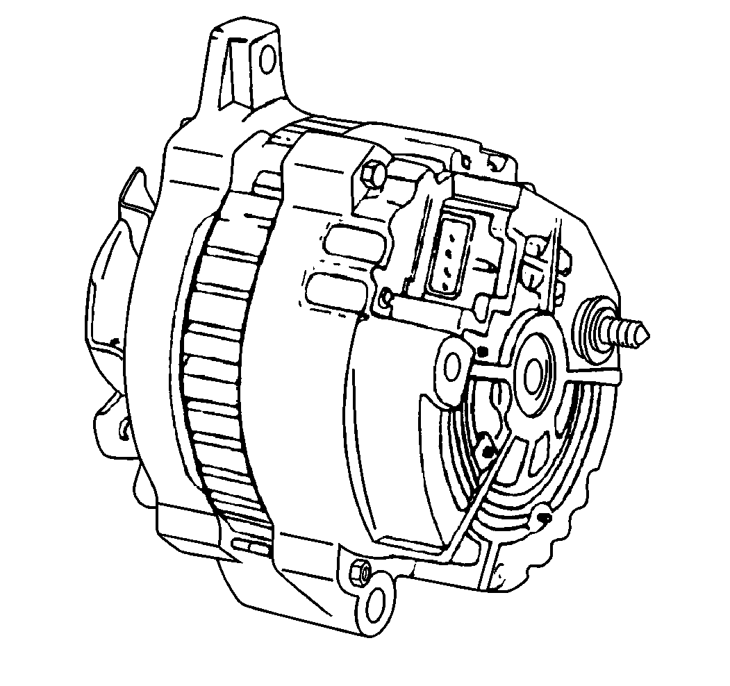
The CS-series generators feature a high ampere output per pound of weight.

On the CS-130 generator, the CS stands for Charging Systems. The 130 indicates the outside diameter of the stator laminations in millimeters.

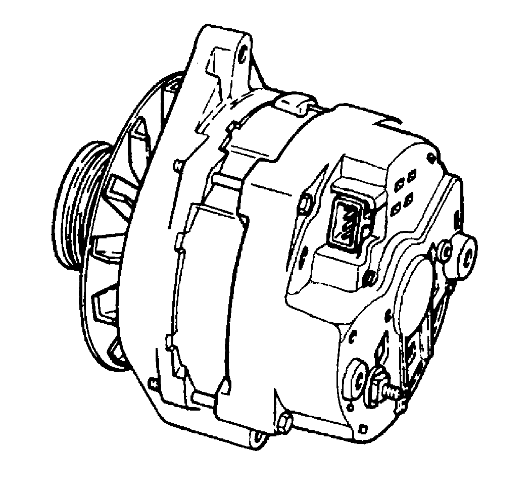
The CS-144 generator is a larger version of the CS-130. The 144 indicates the outside diameter of the stator laminations in millimeters. Unlike the CS-130, the CS-144 is serviceable.
This generator has an integral regulator. This generator does not have a diode trio. The following components are electrically similar to other CS-series generators:
| • | The delta stator |
| • | The rectifier bridge |
| • | The rotor with slip rings and brushes |
A conventional fan and pulley is used. An internal fan cools the following components:
| • | The slip rings |
| • | The end frame |
| • | The rectifier bridge |
| • | The regulator |
The charging indicator activates when the ignition (gasoline engine) or engine control (diesel engine) switch is closed. The charging indicator goes out when the engine is starting and running. If the charge indicator is ON with the engine running, a charging system problem is indicated. The indicator glows at full brilliance (not half lit) if any of the following conditions exist:
| • | Any charging problem occurs. |
| • | The system voltage is too high. |
| • | The system voltage is too low. |
The regulator voltage setting varies with temperature. The regulator voltage setting limits system voltage by controlling rotor field current. The regulator voltage setting switches the rotor field current on and off at a fixed frequency of about 400 cycles per second. Obtain the correct average field current for proper system voltage control by varying ON-OFF time. At high engine speeds, ON time may be 10 percent and OFF time may be 90 percent. At low engine speeds, with high electrical loads, ON time may be 90 percent and OFF time may be 10 percent.
The regulator has four terminals, P, L, I, and S. The S terminal monitors battery voltage so the regulator can maintain an adequate voltage output. The I terminal performs the following actions:
| • | Senses when the ignition switch is in the ON position |
| • | Turns on the regulator. |
| • | Allows field current to flow. |
The L terminal is wired through the charging indicator lamp. The L terminal senses the ignition switch is in the ON or the START position. The P terminal provides a timing pulse for engine startup to the alarm module.
No periodic maintenance or adjustment is required on the generator. The CS-130 is serviceable by complete replacement only. The CS-130 generator should not be disassembled for any reason.
CS-144 Operating Principles
The regulator voltage setting varies with temperature. The regulator voltage setting limits system voltage by controlling rotor field current. The regulator voltage setting switches the rotor field current on and off at a fixed frequency of about 400 cycles per second. Obtain the correct average field current for proper system voltage control by varying ON-OFF time. At high engine speeds, ON time may be 10 percent and OFF time may be 90 percent. At low engine speeds, with high electrical loads, ON time may be 90 percent and OFF time may be 10 percent.
The regulator has P, L, I and S terminals. The P terminal connects internal to the stator. The S terminal monitors batter voltage so the regulator can maintain an adequate voltage output. If the S terminal does not connect externally, the regulator uses internal regulator voltage for control.
both the L and the I terminals serve in order to turn on the regulator and allow field current to flow when the switch is closed. The I terminal may connect either directly to the switch or through a resistor. The I circuit may be used with or without the L circuit (anything connected to the L terminal). The L terminal must connect through an external resistor when used. The charging system indicator lamp is a proper external resistor for this purpose. the regulator grounds the L terminal and activates the indicator lamp when one of the following generator faults is detected:
| • | Excessive voltage |
| • | Reduced voltage |
| • | Lack of rotation |
