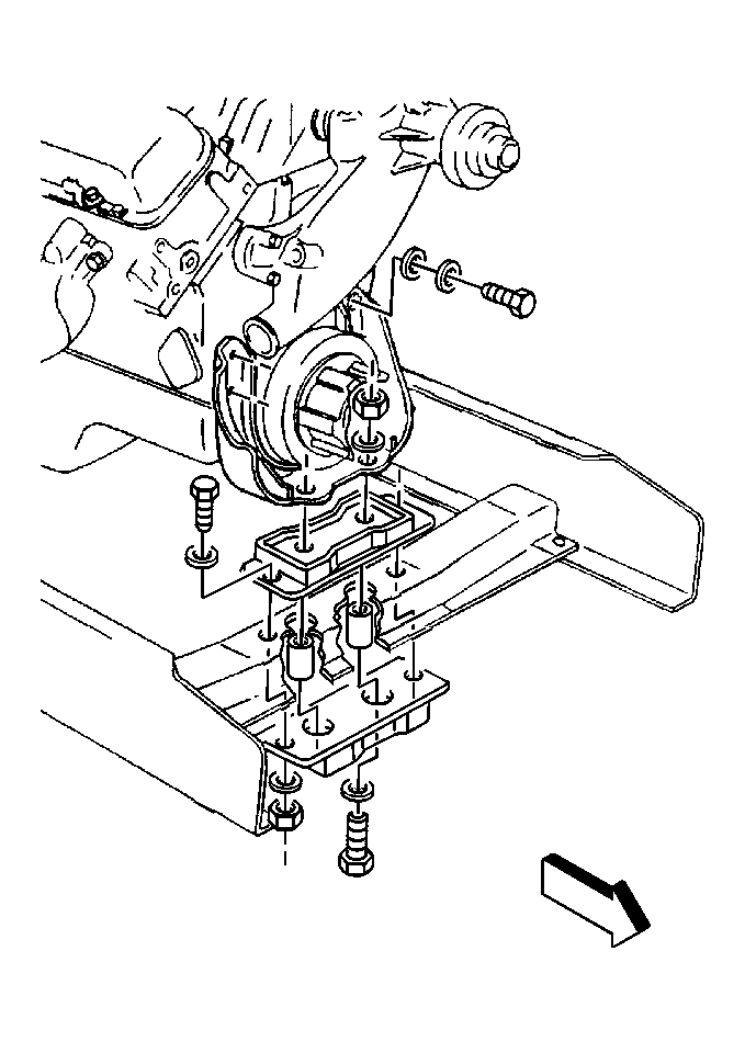
Engine Mount Replacement Front Mount
Removal Procedure
Important: Do not support engine by the oil pan assembly. Damage to the oil pan
could occur.

- Support the engine block
with a suitable stand.
- Remove the bolts and nuts from the engine mount.
- Remove the bolts and nuts from the engine mount to the engine
mount bracket.
- Raise the engine just high enough to remove the engine mount.
- Remove the engine mount from the front crossmember.
- Remove the engine mount spacers from in the front crossmember.
Installation Procedure
Important: Apply a barrier coating of a good corrosion inhibiting compound GM P/N 1052856
or an equivalent to all mating surfaces of dissimilar metals. This will prevent
a chemical reaction from occurring between the two metals. Remove the old
sealer with a putty knife.

- Install the spacers in
the front crossmemeber.
- Install the mounting bracket bolt and washers.
Notice: Use the correct fastener in the correct location. Replacement fasteners
must be the correct part number for that application. Fasteners requiring
replacement or fasteners requiring the use of thread locking compound or sealant
are identified in the service procedure. Do not use paints, lubricants, or
corrosion inhibitors on fasteners or fastener joint surfaces unless specified.
These coatings affect fastener torque and joint clamping force and may damage
the fastener. Use the correct tightening sequence and specifications when
installing fasteners in order to avoid damage to parts and systems.
- Install the nuts
to the bolts.
Tighten
Tighten the nut to 37 N·m (27 lb ft).
Important: Make sure that the center bond cushions compress properly.
- Install the engine mount through bolt and the nut (if used).
Tighten
Tighten the nut to 110 N·m (81 lb ft).
- Remove the lifting device.
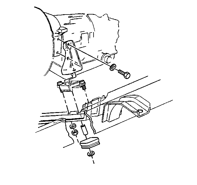
Engine Mount Replacement Rear Mount 6.0 with M/T
Removal Procedure

- Disconnect any of the following that may sustain damage while raising the
engine:
| • | Other susceptible components |
- Remove the engine mounting through bolt and the nut as required.
Notice: When raising or supporting the engine for any reason, do not use a jack
under the oil pan, any sheet metal, or crankshaft pulley. Jacking against
the oil pan will damage it or cause it to be bent against the screen because
of the small clearance between the oil pan and the oil pump screen. Raise
the rear of the power plant only high enough to permit removal of the upper
cushion, and provide safety blocking to prevent tipping and possible damage
to front mountings. Be careful not to damage control linkages and wiring.
- Provide a jack in order to safely raise the rear of the engine or the
transmission, as necessary.
- Remove the cushions and the spacers as needed.
- Remove the following components (as used):
Important: Support any vehicle components that are held in place by the vehicle
mounting fasteners before removing the fasteners.
- Remove the mounting bracket.
Installation Procedure

Important: Apply a barrier coating of a good corrosion inhibiting compound GM P/N 1052856
or an equivalent to all mating surfaces of dissimilar metals. This will prevent
a chemical reaction from occurring between the two metals. Remove the old
sealer with a putty knife.
- Install the mounting bracket to the engine and the frame.
Notice: Use the correct fastener in the correct location. Replacement fasteners
must be the correct part number for that application. Fasteners requiring
replacement or fasteners requiring the use of thread locking compound or sealant
are identified in the service procedure. Do not use paints, lubricants, or
corrosion inhibitors on fasteners or fastener joint surfaces unless specified.
These coatings affect fastener torque and joint clamping force and may damage
the fastener. Use the correct tightening sequence and specifications when
installing fasteners in order to avoid damage to parts and systems.
- Install the following
components:
Tighten
Tighten the nuts to 37 N·m (27 lb ft).
- Lubricate the center bond cushions with water before installing.
- Install the cushions and the spacers (as required).
- Lower the engine in order to install the through bolt.
- Install the following components as required:
- Install the nut (as required).
Tighten
Tighten the through bolt or the nut to 196 N·m (145 lb ft).
Ensure that the center bond cushion compresses properly.
- Connect the following components:
| • | Any components that you disconnected. |
- Remove the lifting device.
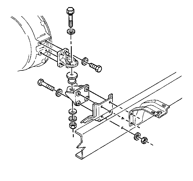
Engine Mount Replacement Rear Mount M/T643G or MT653
Removal Procedure

- Disconnect any of the following that may sustain damage while raising the
engine:
| • | Other susceptible components |
- Remove the engine mounting through bolt and the nut as required.
Notice: When raising or supporting the engine for any reason, do not use a jack
under the oil pan, any sheet metal, or crankshaft pulley. Jacking against
the oil pan will damage it or cause it to be bent against the screen because
of the small clearance between the oil pan and the oil pump screen. Raise
the rear of the power plant only high enough to permit removal of the upper
cushion, and provide safety blocking to prevent tipping and possible damage
to front mountings. Be careful not to damage control linkages and wiring.
- Provide a jack in order to safely raise the rear of the engine or the
transmission, as necessary.
- Remove the cushions and the spacers as needed.
- Remove the following components (as used):
Important: Support any vehicle components that are held in place by the vehicle
mounting fasteners before removing the fasteners.
- Remove the mounting bracket.
Installation Procedure

Important: Apply a barrier coating of a good corrosion inhibiting compound GM P/N 1052856
or an equivalent to all mating surfaces of dissimilar metals. This will prevent
a chemical reaction from occurring between the two metals. Remove the old
sealer with a putty knife.
- Install the mounting bracket to the engine and the frame.
Notice: Use the correct fastener in the correct location. Replacement fasteners
must be the correct part number for that application. Fasteners requiring
replacement or fasteners requiring the use of thread locking compound or sealant
are identified in the service procedure. Do not use paints, lubricants, or
corrosion inhibitors on fasteners or fastener joint surfaces unless specified.
These coatings affect fastener torque and joint clamping force and may damage
the fastener. Use the correct tightening sequence and specifications when
installing fasteners in order to avoid damage to parts and systems.
- Install the following
components:
Tighten
Tighten the nuts to 37 N·m (27 lb ft).
- Lubricate the center bond cushions with water before installing.
- Install the cushions and the spacers (as required).
- Lower the engine in order to install the through bolt.
- Install the following components as required:
- Install the nut (as required).
Tighten
Tighten the through bolt or the nut to 196 N·m (145 lb ft).
Ensure that the center bond cushion compresses properly.
- Connect the following components:
| • | Any components that you disconnected |
- Remove the lifting device.
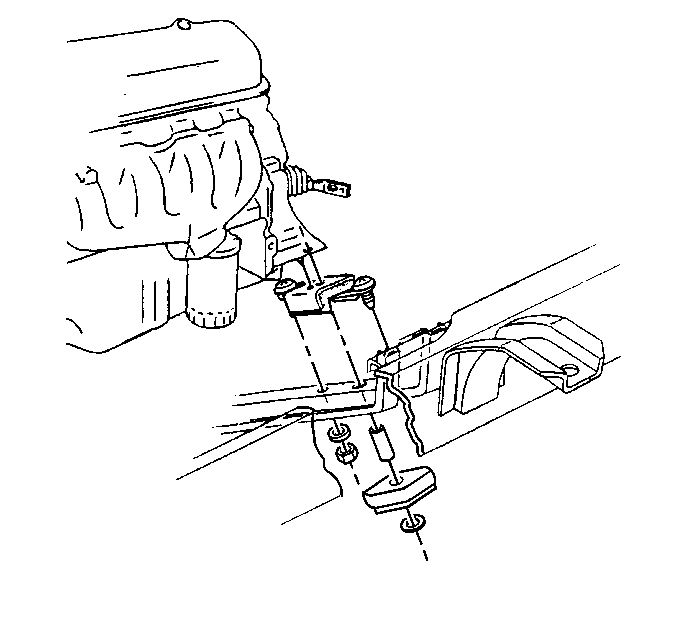
Engine Mount Replacement Rear Mount AT545 Trans
Removal Procedure

- Disconnect any of the following that may sustain damage while raising the
engine:
| • | Other susceptible components |
- Remove the engine mounting through bolt and the nut as required.
Notice: When raising or supporting the engine for any reason, do not use a jack
under the oil pan, any sheet metal, or crankshaft pulley. Jacking against
the oil pan will damage it or cause it to be bent against the screen because
of the small clearance between the oil pan and the oil pump screen. Raise
the rear of the power plant only high enough to permit removal of the upper
cushion, and provide safety blocking to prevent tipping and possible damage
to front mountings. Be careful not to damage control linkages and wiring.
- Provide a jack in order to safely raise the rear of the engine or the
transmission, as necessary.
- Remove the cushions and the spacers as needed.
- Remove the following components (as used):
Important: Support any vehicle components that are held in place by the vehicle
mounting fasteners before removing the fasteners.
- Remove the mounting bracket.
Installation Procedure

Important: Apply a barrier coating of a good corrosion inhibiting compound GM P/N 1052856
or an equivalent to all mating surfaces of dissimilar metals. This will prevent
a chemical reaction from occurring between the two metals. Remove the old
sealer with a putty knife.
- Install the mounting bracket to the engine and the frame.
Notice: Use the correct fastener in the correct location. Replacement fasteners
must be the correct part number for that application. Fasteners requiring
replacement or fasteners requiring the use of thread locking compound or sealant
are identified in the service procedure. Do not use paints, lubricants, or
corrosion inhibitors on fasteners or fastener joint surfaces unless specified.
These coatings affect fastener torque and joint clamping force and may damage
the fastener. Use the correct tightening sequence and specifications when
installing fasteners in order to avoid damage to parts and systems.
- Install the following
components:
Tighten
Tighten the nuts to 37 N·m (27 lb ft).
- Lubricate the center bond cushions with water before installing.
- Install the cushions and the spacers (as required).
- Lower the engine in order to install the through bolt.
- Install the following components as required:
- Install the nut (as required).
Tighten
Tighten the through bolt or the nut to 196 N·m (145 lb ft).
Ensure that the center bond cushion compresses properly.
- Connect the following components:
| • | Any components that you disconnected |
- Remove the lifting device.


