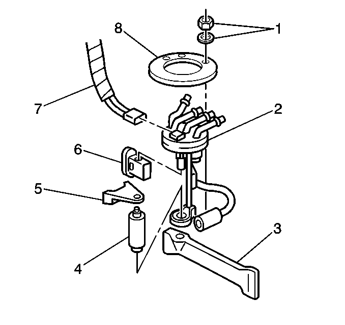
Removal Procedure
Caution: Unless directed otherwise, the ignition and start switch must be in the OFF or LOCK position, and all electrical loads must be OFF before servicing
any electrical component. Disconnect the negative battery cable to prevent an electrical spark should a tool or equipment come in contact with an exposed electrical terminal. Failure to follow these precautions may result in personal injury and/or damage to
the vehicle or its components.
- Remove the
negative battery cable.
- Relieve the fuel system pressure. Refer to
Fuel Pressure Relief
.
- Remove the fuel feed and return pipe quick-connect fittings at
fuel sender assembly. Refer to
Metal Collar Quick Connect Fitting Service
and
Plastic Collar Quick Connect Fitting Service
.

- Remove the fuel sender
assembly electrical connector (7).
- Remove the six nuts and washers (1) retaining the fuel
sender assembly lock ring (8).
- Remove the lock ring, the sender assembly (2), and the seal.
- Remove the Fuel Tank.
Support and slide out the fan until the fuel sender assembly to clear
the cab.
- Remove the fuel pump electrical connector.
- Remove the fuel pump (4) from the sender assembly (2).
| 9.1. | Pull the fuel pump up into the attaching hose while pulling outward
from the bottom support. |
| 9.2. | Do not damage the rubber insulator or the strainer. |
- Inspect the fuel pump attaching hose for signs of deterioration.
- Inspect the rubber sound insulation at the bottom of the pump.
Installation Procedure

- Install the fuel pump
assembly (4) into the attaching hose.
- Install the fuel pump electrical connector.
Important: Care should be taken not to fold over or twist the strainer (3), when
installing the sender assembly as this will restrict fuel flow.
- Install the new seal, sender assembly (2), and lock ring (8).
Make sure the lock ring alignment holes fit over the tabs on the tank.
- Install the six washers and nuts (1) retaining the fuel
sender assembly lock ring.
- Install the fuel tank.
Slide the tank into the original position
- Install the fuel feed and return pipe quick-connect fittings.
Refer to
Metal Collar Quick Connect Fitting Service
and
Plastic Collar Quick Connect Fitting Service
.
- Install the fuel sender assembly electrical connector (7).
- Install the negative battery cable.
- Check for fuel leaks using the following procedure:
| 9.1. | Turn the ignition switch to ON position for 2 seconds. |
| 9.2. | Turn the ignition switch to OFF for 10 seconds. |
| 9.3. | Turn the ignition switch to ON position. |
| 9.4. | Check for fuel leaks. |


