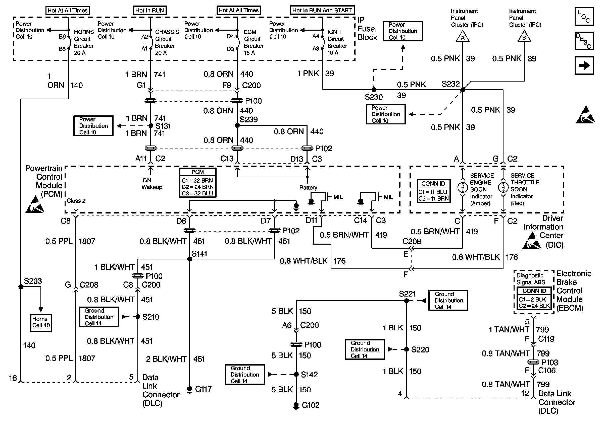
Refer to Engine Controls Schematics
Cell 22: Power and Grounding, MIL and Serial Data Circuits

.
Circuit Description
There should always be a steady Malfunction Indicator Lamp (MIL) when the ignition is ON and engine OFF. Battery ignition voltage is supplied to the lamp. The PCM will turn the lamp ON by grounding the ignition feed circuit.
Diagnostic Aids
If the engine cranks but will not run, check:
| • | Continuous battery-fuse or fusible link for open. |
| • | PCM ignition fuse for open. |
| • | Battery Feed circuit to PCM for open. |
| • | Ignition Feed circuit to PCM for open. |
| • | Poor connection to PCM. |
Test Description
The number(s) below refer to step number(s) on the Diagnostic Table.
-
This step will isolate the problem in the MIL control circuit.
-
If the Battery Feed, Ignition Feed and Diagnostic Test circuits have voltage, the PCM connections, grounds, or PCM are malfunctioning.
-
Refer to PCM terminal end view in this section for PCM pin locations of ground circuits.
-
If the fuse/fusible link is open, refer to PCM Wiring Diagram for complete circuit.
Step | Action | Value(s) | Yes | No |
|---|---|---|---|---|
1 | Was the Powertrain On-Board Diagnostic (OBD) System Check performed? | -- | ||
2 | Attempt to start the engine. Does the engine start? | -- | ||
3 | Check the fuse number 4. Is the fuse OK? | -- | ||
4 | Turn the ignition ON. Probe the ignition feed circuit at the cluster connector with a test light to ground. Is the test light ON? | -- | ||
Is the MIL ON? | -- | |||
Check the PCM Ignition Feed and Battery Feed fuses. Are both of the fuses OK? | -- | |||
7 |
Is the test light ON both circuit? | -- | ||
Was a problem found? | -- | |||
9 |
Was a problem found? | -- | ||
10 |
Was a problem found? | -- | ||
11 | Repair open in the ignition feed circuit to the cluster connector. Is the action complete? | -- | -- | |
Locate and repair open in the PCM battery feed circuit or the PCM ignition feed circuit as necessary. Is the action complete? | -- | -- | ||
13 | Locate and repair short to ground in the PCM Ignition Feed circuit or the PCM Battery Feed circuit as necessary. Is the action complete? | -- | -- | |
14 | Locate and repair short to ground in the instrument cluster Ignition Feed circuit. Is the action complete? | -- | -- | |
15 | Replace the PCM. Important: If the PCM is faulty, The new PCM must be programmed. Refer to Powertrain Control Module Replacement/Programming . Is the action complete? | -- | -- | |
16 |
Was a problem found? | -- | ||
17 |
Is the bulb OK? | -- | ||
18 | Replace the MIL bulb. Is the action complete? | -- | -- | |
19 | Replace the instrument cluster. Is the action complete? | -- | -- | |
20 |
Does the engine start and continue to run? | -- | ||
21 |
Are any DTCs displayed? | -- | Go to the Applicable DTC Table | |
22 | Using the Scan Tool, select Capture Info, Review Info. Are any DTCs displayed that have not been diagnosed? | -- | Go to the Applicable DTC Table. | System OK |
