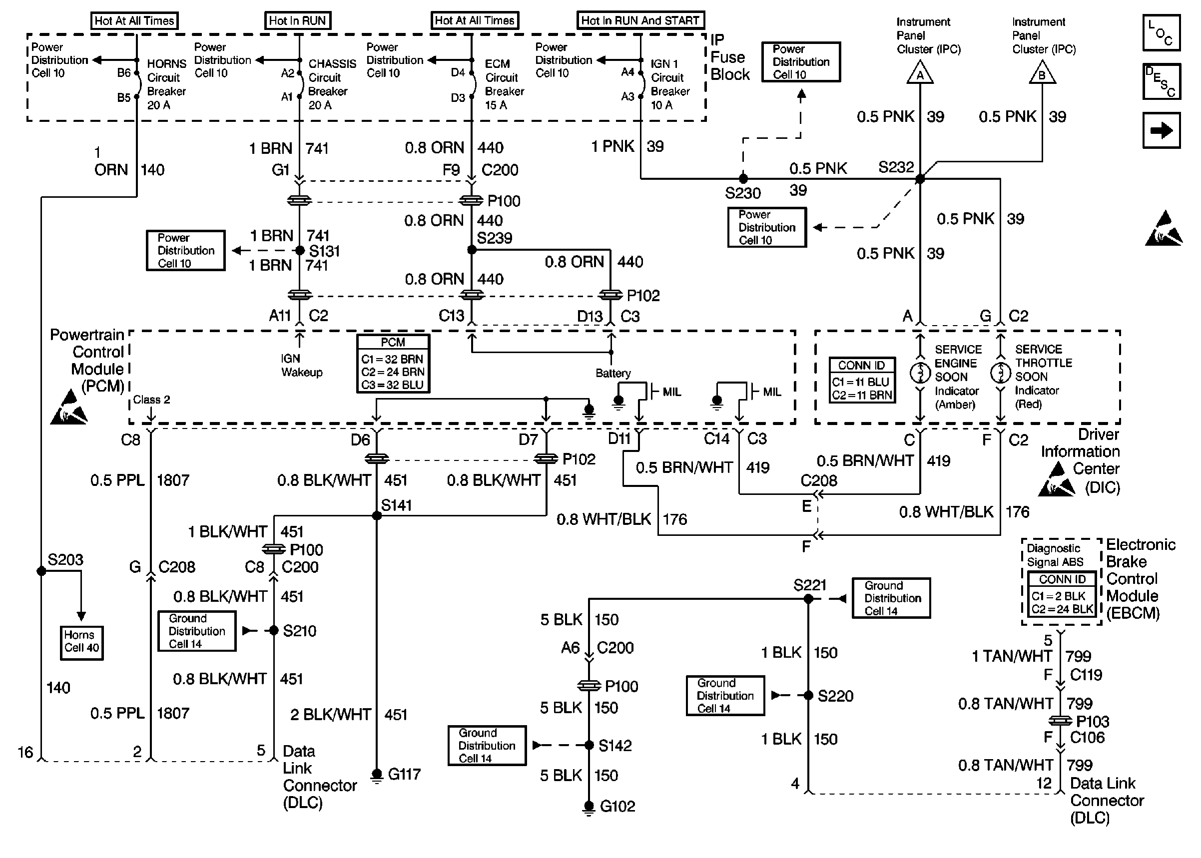
Refer to Engine Controls Schematics
Cell 22: Power and Grounding, MIL and Serial Data Circuits

.
Circuit Description
There should always be a steady Malfunction Indicator Lamp (MIL) when the ignition is ON and engine OFF. Battery ignition voltage is supplied to the lamp. The PCM will turn the lamp ON by grounding the ignition feed circuit.
Test Description
The number(s) below refer to the step number(s) on the Diagnostic Table.
-
This step verifies if the problem in the scan tool or the vehicle.
-
If the resistance reading is below 10 ohms, this indicates that the serial data circuit or a controller module that shares the circuit is shorted to ground or shorted internally.
-
By disconnecting each controller module that shares the serial data circuit and re-checking the resistance can determine if the shared controller module internally.
-
This step checks to determine if the serial data circuit is shorted to voltage.
-
A resistance reading under 10 ohms indicates that the circuit has continuity. A high resistance reading indicates an open in the circuit.
Step | Action | Value(s) | Yes | No | ||||||
|---|---|---|---|---|---|---|---|---|---|---|
1 | Was the Powertrain On-Board Diagnostic (OBD) System Check performed? | -- | ||||||||
Does the PCM communicate with the scan tool? | -- | |||||||||
3 |
Does the scan tool communicate with the PCM? | -- | ||||||||
4 | The scan tool may be malfunctioning. Refer to the scan tool instruction manual. Is the action complete? | -- | -- | |||||||
Is the resistance less than the specified value? | 10 Ohms | |||||||||
Does disconnecting one of the modules cause the resistance to be greater than the specified value? | 10 Ohms | |||||||||
Is the voltage less than the specified value? | 1.0 V | |||||||||
Is the resistance less than the specified value? | 10 Ohms | |||||||||
9 |
Was a problem found? | -- | ||||||||
10 |
Was a problem found? | -- | ||||||||
11 | Repair the intermittent short or open on the serial data circuit. Is the action complete? | -- | -- | |||||||
12 | Repair the short to voltage on the serial data circuit. Is the action complete? | -- | -- | |||||||
13 | Repair the open in the serial data circuit. Is the action complete? | -- | -- | |||||||
14 | Repair the short to ground on the serial data circuit. Is the action complete? | -- | -- | |||||||
15 | Replace the appropriate module that caused the resistance increase. Is the action complete? | -- | -- | |||||||
16 | Replace the PCM. Important: The new PCM must be programmed. Refer to Powertrain Control Module Replacement/Programming . Is the action complete? | -- | -- | |||||||
17 | Operate the vehicle within the conditions the symptom was noted. Does the system operate properly? | -- |
