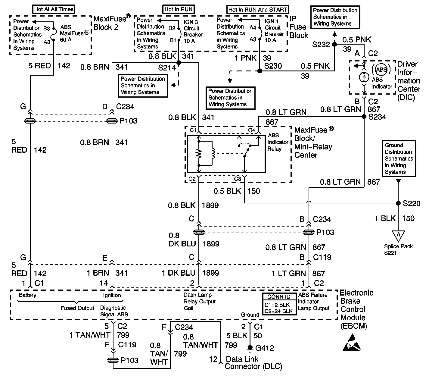
Circuit Description
The amber ABS indicator lamp operates in two modes; normal and backup. In the normal mode, ignition voltage is supplied to the ABS indicator lamp through the IGN SW fuse. The indicator is normally on unless the EBCM switches the indicator off, by energizing the ABS indicator lamp relay. The EBCM tests the ABS indicator lamp circuit with a 2 second bulb check, when the ignition is turned to RUN or the vehicle is started, the EBCM turns the indicator off. If the EBCM senses that a fault has occurred, it will set a DTC and light the ABS indicator lamp by de-energizing the ABS indicator lamp relay. In the backup mode, the ABS indicator lamp relay circuit will ensure that the ABS indicator lamp is illuminated, if the 24-way EBCM connector is disconnected or poorly seated, or if the EBCM has failed during normal operation. If either of these fault conditions occur, the ABS indicator lamp relay will de-energize, which connects a ground path to the ABS indicator lamp circuit through terminals C1 and C2 of the ABS indicator lamp relay. This system ensures that the ABS indicator lamp will always be turned on if the following conditions exist:
| • | Short to ground in CKT 867 |
| • | Open or high resistance in CKT 1899 |
| • | Open or high resistance in CKT 39 |
| • | The ABS indicator lamp relay is faulty |
| • | The EBCM is faulty |
Diagnostic Aids
If the ABS indicator lamp is on always with no DTCs set (never turns off with the vehicle started or with the ignition switch in the RUN position), there is a short to ground in CKT 867 between the instrument cluster and the EBCM, or there is a fault in the ABS indicator lamp relay circuit.
Test Description
The numbers below refer to the steps in the diagnostic table:
-
This step checks for normal operation of the ABS indicator lamp.
-
This step manually (with fused jumper) turns off the ABS indicator lamp.
Step | Action | Value(s) | Yes | No |
|---|---|---|---|---|
1 | Was the Diagnostic System Check performed? | -- | Go to Diagnostic System Check | |
Does the ABS indicator lamp turn off? | -- | |||
Does the ABS indicator lamp turn off? | -- | |||
4 | Using a J 39200 , measure the voltage between the ABS indicator relay harness connector terminal C1 and ground. Is the voltage measured equal to or greater than the specified value? | 10 V | ||
5 | Using a J 39200 , measure the resistance between the relay center harness connector terminal C2 and the EBCM harness connector terminal 2. Is the resistance within the specified range? | 0-2 ohms | ||
6 |
Is the ABS indicator lamp on constantly? | -- | Go to Diagnostic Aids | |
7 | Repair the short to ground in CKT 867. Refer to Wiring Repairs in Wiring Systems. Is the repair complete? | -- | Go to Diagnostic System Check | -- |
8 | Repair the open or the high resistance in CKT 341. Refer to Wiring Repairs in Wiring Systems. Is the repair complete? | -- | Go to Diagnostic System Check | -- |
9 | Replace the ABS indicator relay. Is the repair complete? | -- | Go to Diagnostic System Check | -- |
10 | Repair the open or the high resistance in CKT 1899. Refer to Wiring Repairs in Wiring Systems. Is the repair complete? | -- | Go to Diagnostic System Check | -- |
11 | Replace the EBCM. Refer to Electronic Brake Control Module Replacement . Is the repair complete? | -- | Go to Diagnostic System Check | -- |
