Air Brake System Valve
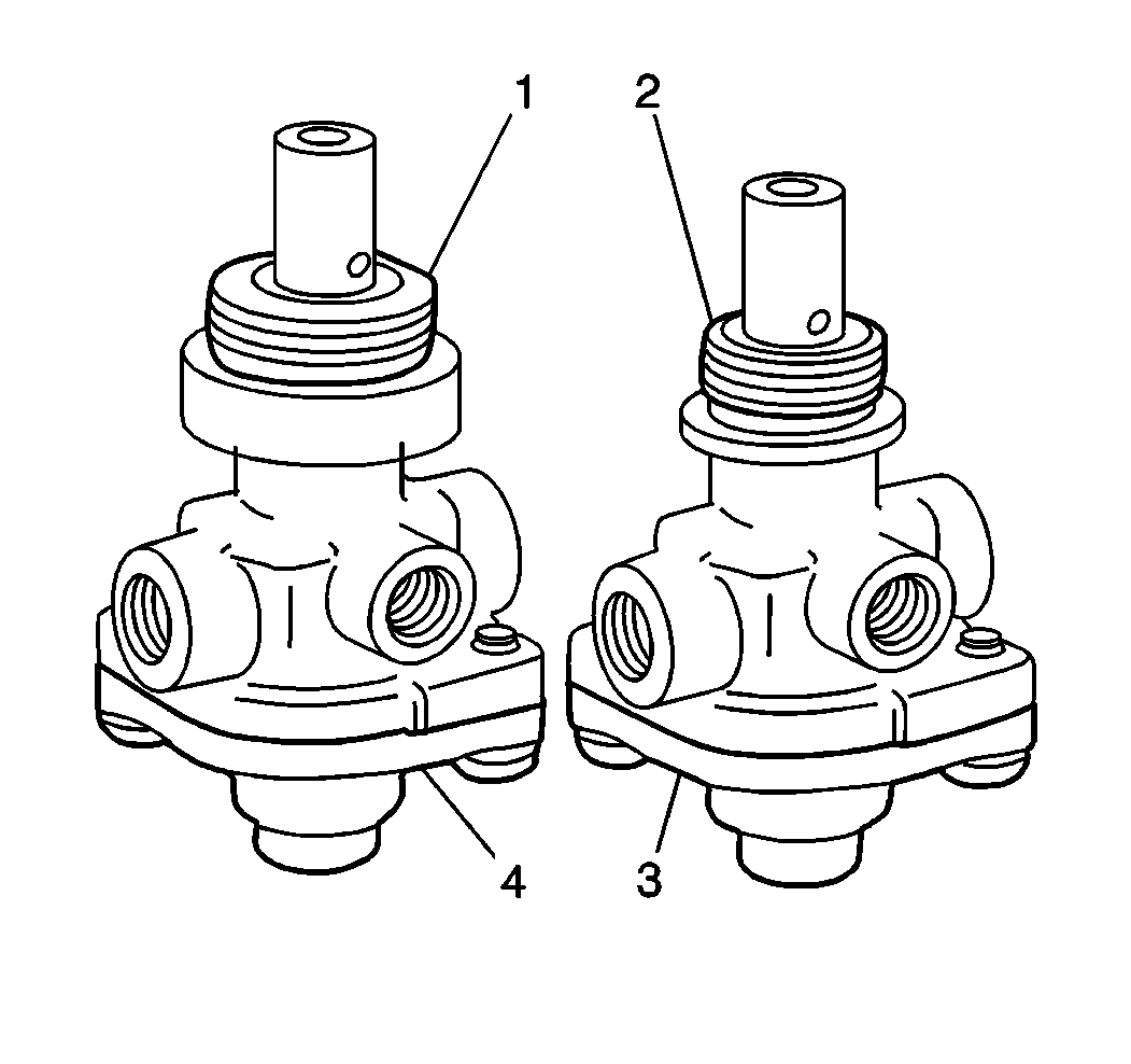
The system park valve (4) is used on all models with air brakes. The valve is mounted in the dash on the right side of the instrument cluster. The valve has a yellow diamond shaped control knob.
The vehicle spring brakes are applied when you pull out the knob. If the vehicle has trailer controls, the trailer air supply line exhausts when you pull out the knob. Pushing the knob in releases the spring brake chambers and charges the trailer air supply.
The knob will stay pushed in as long as the supply pressure is 310 kPa (45 psi) or more. When air pressure drops below 138 kPa (20 psi), the valve spring causes the knob to pop out.
The system park valve (4) has:
| • | A supply port |
| • | A delivery port |
| • | An exhaust port |
| • | A control knob with a pop-out spring |
When the knob is pulled out, the exhaust port is blocked and the supply air flows out of the delivery port.
Front Axle Limiting (Ratio) Valve
The front axle limiting (ratio) valve is optional on all models. The front axle limiting (ratio) valve mounts to the front chassis cross member and automatically limits air pressure to the front service brake chambers during normal braking.
The following ports are identified by embossed letters:
| • | The supply port |
| • | The delivery port |
| • | The exhaust port |
The limiting valve supply port is connected to the application valve front service delivery port. The delivery port connects to the quick release valve supply port. The exhaust port points down.
Air pressure entering the supply port decreases 50 percent before leaving the delivery port. This reduction occurs only when brake application pressure to the supply port of the limiting valve is 0-275 kPa (0-40 psi). Application valve pressure between 276-413 kPa (40-60 psi) is reduced less than 50 percent. Application valve pressure above 413 kPa (30 psi) at the supply port is reduced to 103 kPa (15 psi) at the delivery port; 448 kPa (65 psi) at the supply port remains at 448 kPa (65 psi)
Inflation Valve
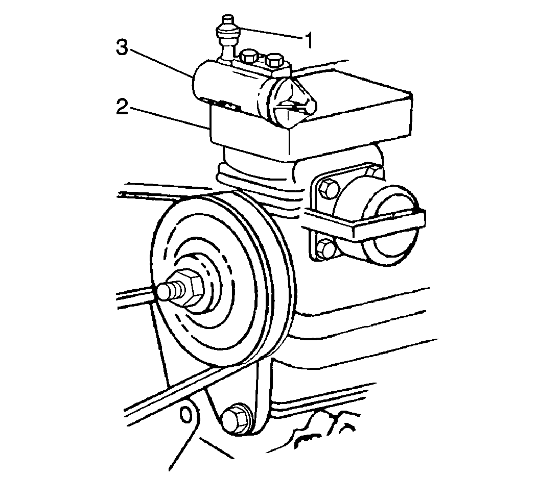
The inflation valve (1) is located on the air compressor governor (3). The valve is used in order to fill the air system from an external source.
The inflation valve is a check valve and fitting for an external air hose connection. Ensure that a cap is on the stem in order to keep out dirt and other contaminants.
Moisture Ejector Valve
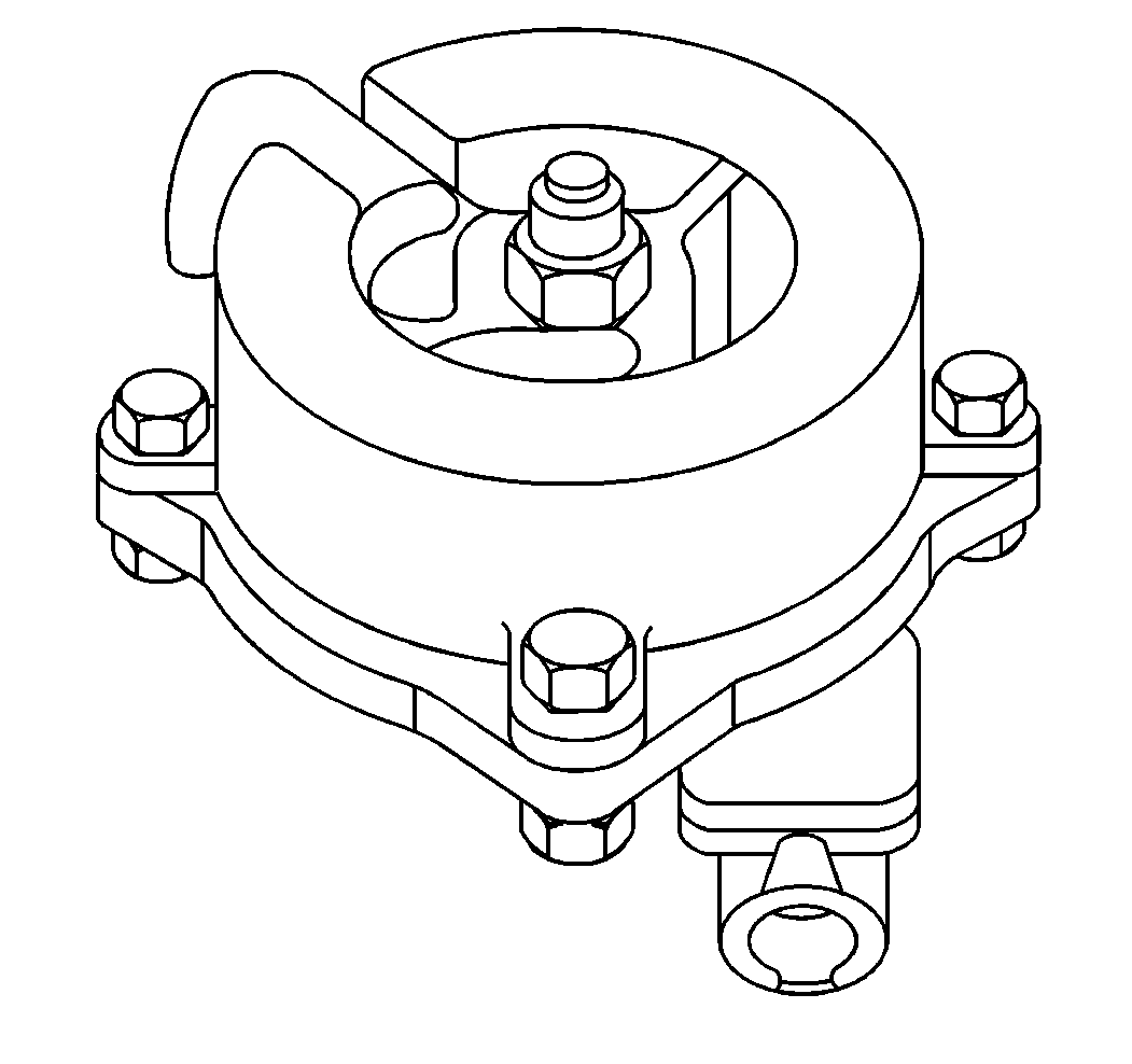
The moisture ejector valve is optional. Some moisture ejector valves include a heater and thermostat attached underneath the valve body.
The valve automatically drains moisture and contaminants from the supply reservoir. The valve mounts to the reservoir at the valve supply port with the exhaust port pointing down.
The supply and exhaust ports are normally closed. When the air compressor turns on in order to increase reservoir pressure, the supply port opens. This action allows air and contaminants to collect in the sump of the moisture ejector valve. The supply port remains open until the reservoir pressure reaches the governor cut-out pressure. The valve spring then closes the supply port.
When the supply reservoir pressure drops about 14 kPa (2 psi), the sump cavity pressure opens the exhaust port and ejects the moisture and contaminants. The exhaust port remains open until the sump pressure is exhausted. The length of time the exhaust port remains open and the amount of moisture and contaminants ejected depends on sump pressure and reservoir pressure drop.
The valve can be operated manually by pushing a wire up the exhaust port. Remove the wire when you are finished draining.
On valves with a heating unit, the heater and the thermostat switch ON when the valve body temperature is 7°C (45°F) and switches OFF at 29°C (85°F).
Pressure Protection Valve
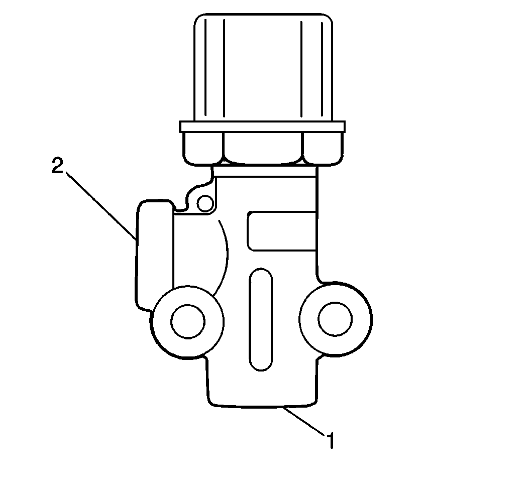
The pressure protection valve is used on vehicles with air accessories or provisions for air accessories. The valve is located on the left front service reservoir.
This valve protects the air supply to the brakes if a failure occurs in the accessory equipment. The valve has a supply port (2) and delivery port (1).
The valve allows air to flow from the supply port (2) to the delivery port (1) as long as sufficient air pressure is available. If air pressure decreases below the specified closing pressure, the internal regulating spring moves the piston, closing the inlet valve. The remaining air pressure at the supply side remains. The closing pressure is noted on the label attached to the valve.
Quick Release Valve
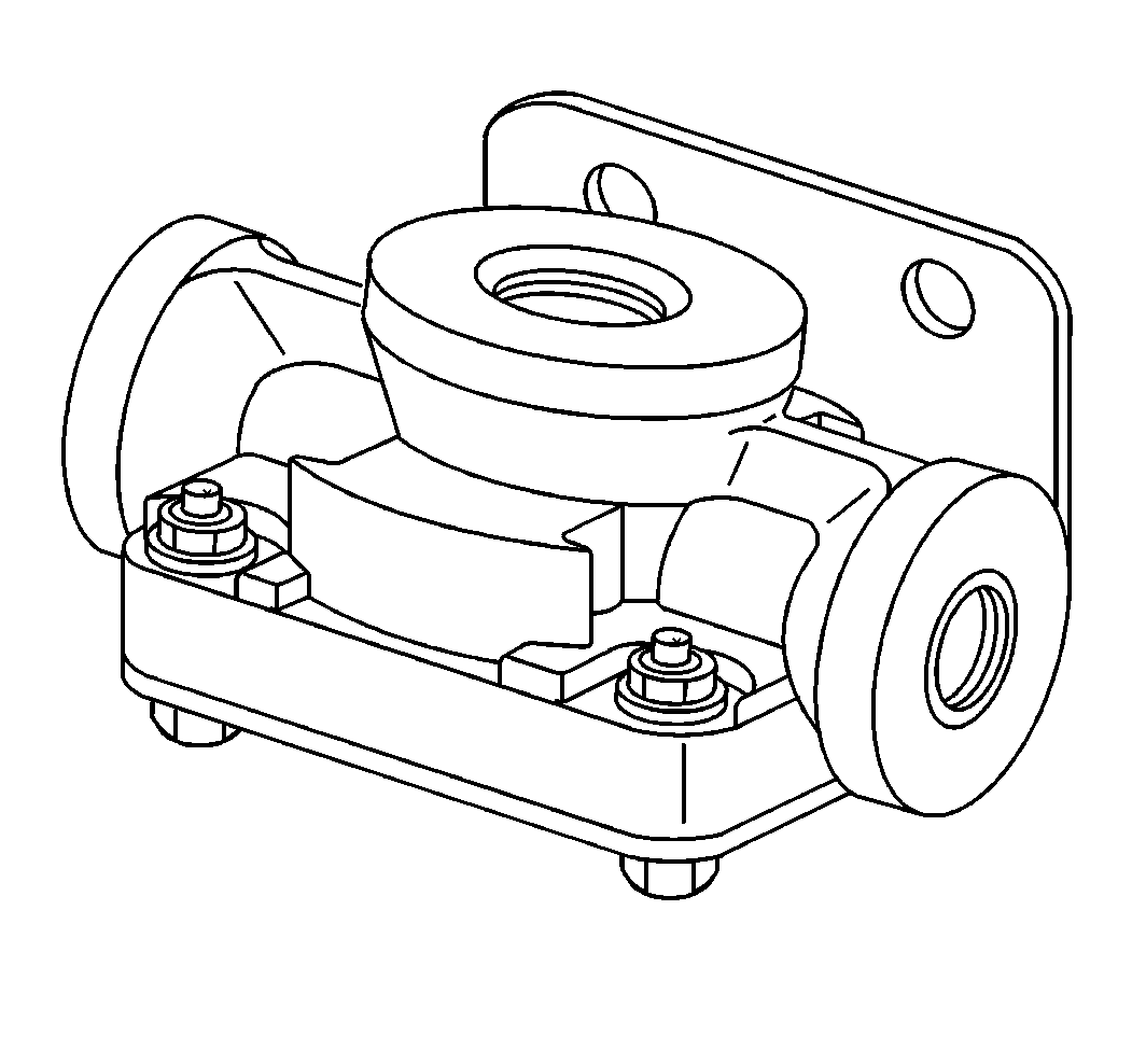
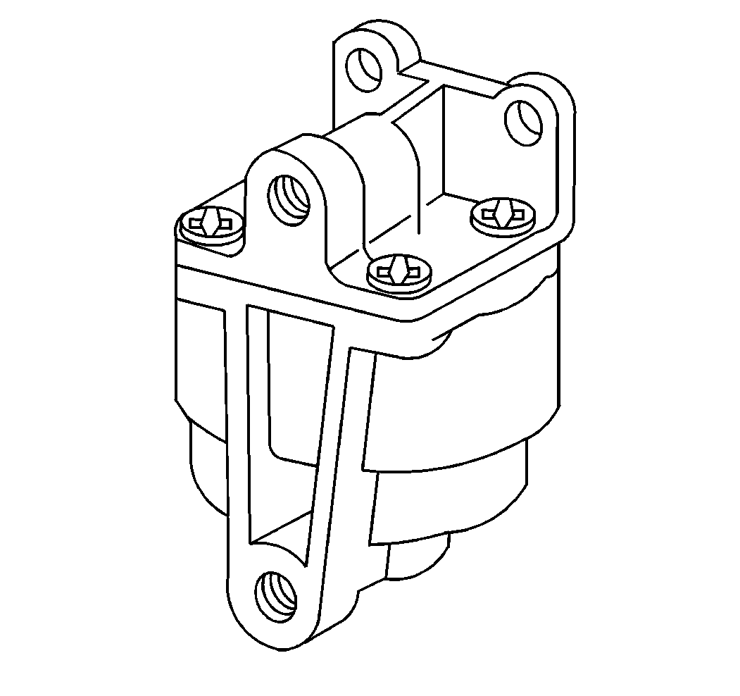
The quick release valve is standard on all models and mounts to a bracket on the front chassis cross member.
When the brakes are applied, supply air flows through the valve and out two delivery ports connected to the service brake chambers at the front wheels. When the foot brake is released, the service brake chamber air at the delivery ports is immediately vented through the exhaust port rather than the dual application valve. The quick release valve reduces the time required to exhaust the brake chamber air compared to the time required to exhaust the air through the dual application valve.
The valve has an internal diaphragm. Applying the brakes sends air pressure to the supply port. The air pressure moves the diaphragm in order to seal the exhaust port and open the two delivery ports. Air flows through the valve to the service brake chambers until they are full. When the air flow stops, the lip of the diaphragm seals the supply port. This sealing action causes the delivered air pressure to be slightly less than the supply pressure. This differential air pressure is typically 7 kPa (1 psi). Releasing the brake pedal causes air from the service brake chambers to raise the diaphragm. This action seals the supply port and opens the exhaust port, venting the service brake chamber air pressure.
Quick Release Valve With Double Check
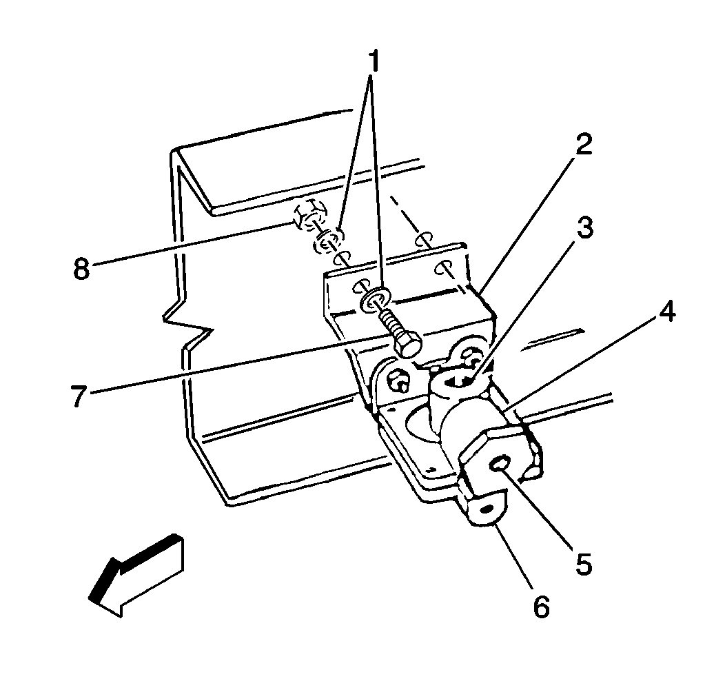
The quick release valve with double check (4) mounts to a bracket (2) near the rear spring brake chamber assemblies.
The system park valve controls the quick release valve, speeding up spring brake application in an emergency situation.
The quick release valve with double check (4) also functions as an anti-compound device. The internal double check diaphragm balances the service brake line pressure and the spring brake line pressure. This condition prevents the service brake chamber and spring brake chamber from compounding their braking forces on the slack adjusters. When you apply the service brake chambers and the spring brake chambers at the same time, the double check diaphragm uses some air from the service brakes in order to partially release spring pressure on the slack adjuster. This condition balances the spring pressure with the service brake line pressure and keeps the slack adjuster from overloading.
The quick release valve with double check (4) has the following components:
| • | A supply port (5) |
| • | A balance port (3) |
| • | A exhaust port |
| • | Two delivery ports (6) |
Applying the system park valve sends air in the supply port (5), out both delivery ports (6), and to the spring brake chambers. When the system park valve pops out in order to apply the spring brake chambers, the supply port (5) and the balance port (3) are sealed and the exhaust port opens. This action vents the spring brake chamber air. Applying the brake pedal while the vehicle is parked causes service air to flow in the balance port (3), through the double check diaphragm, and out the delivery ports (6) to the spring brake chambers.
Relay Valve With Double Check
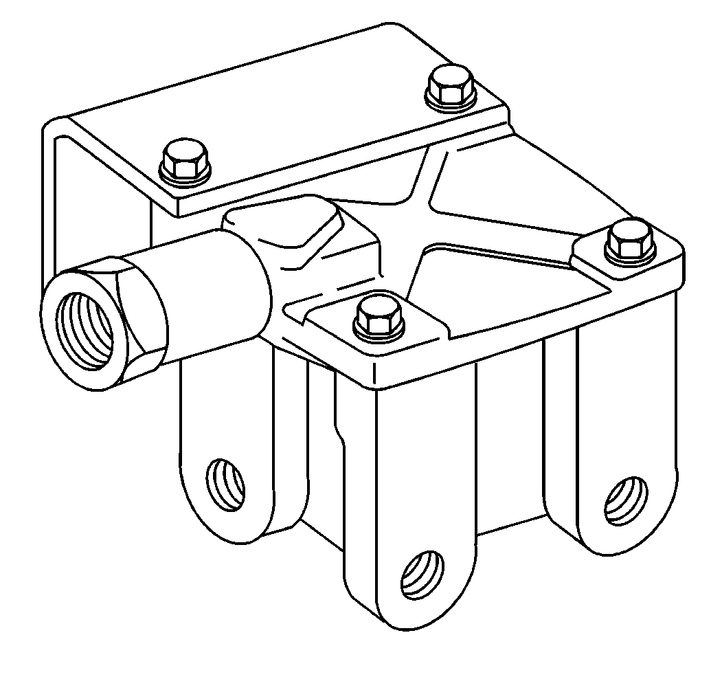
The relay valve with double check is used on vehicles not built as tractors. The relay valve with double check works with the spring brake control valve.
The relay vale is mounted to the frame side rail near the rear axle(s) in order to allow the shortest possible delivery lines to the spring brake chambers.
The valve functions as a quick release valve that delivers or releases air to the spring brake chambers in response to the air pressure from the system park valve.
An internal double check diaphragm balances service brake line pressure and spring brake line pressure. This condition prevents the service brake chamber and the spring brake chamber from compounding their braking forces on the slack adjusters. When you apply the service brake chambers and the spring brake chambers at the same time, the double check diaphragm uses some air from the service brakes in order to partially release spring brake pressure from the slack adjuster. This condition balances the mechanical spring pressure with the service brake line pressure and keeps the slack adjusters from overloading.
The valve has the following components:
| • | A control port |
| • | A balance port |
| • | Two supply ports |
| • | Two delivery ports |
| • | An exhaust port |
The control port connects to the system park valve. The balance port connects to a relay valve delivery line. The control and balance lines are combined through an internal double check diaphragm in order to prevent brake compounding. One of the supply ports connects to the rear axle service reservoir and the other is usually plugged. The delivery ports connect to the spring brake chamber.
When the dual application valve increases air pressure at the control port an internal piston lowers in order to block the exhaust port and gradually open the supply port in relation to piston travel. Supply air enters the chamber on the opposing face of the piston and flows out the delivery ports. With control and supply air on the opposing faces, the piston balances to a position where the two pressures are equalized. Any change in control pressure then causes an equal change in delivery pressure.
Releasing the system park valve takes the control air away. This action causes the piston to rise, close the supply port, and open the exhaust port in the bottom. Air pressure at the delivery ports then quickly vents through the exhaust port.
Proportioning Relay Valve
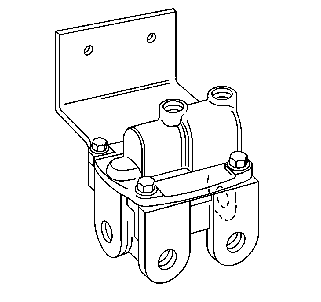
The proportioning relay valve is only used on tractor applications. The proportioning relay valve is a combination of two individual valves in a single housing. The lower portion, or body, of the valve contains a standard service brake relay valve. The upper portion, or cover, houses a brake proportioning valve to reduce normal service brake application pressure when the tractor is not towing a trailer.
The valve mounts to a bracket on the frame sidemember. Air connections are identified by embossed letters. The valve has a supply port connected to the rear reservoir, a service port connected to the dual application valve, control port, and two delivery ports in order to allow air flow to the service brake chambers.
When the tractor is pulling a trailer, the proportioning relay valve serves as a service brake relay valve in order to speed up apply and release time. When the tractor operates without a trailer, the proportioning relay valve reduces air pressure to the rear service brake chambers for improved control and reduced stopping distances.
Safety Valve
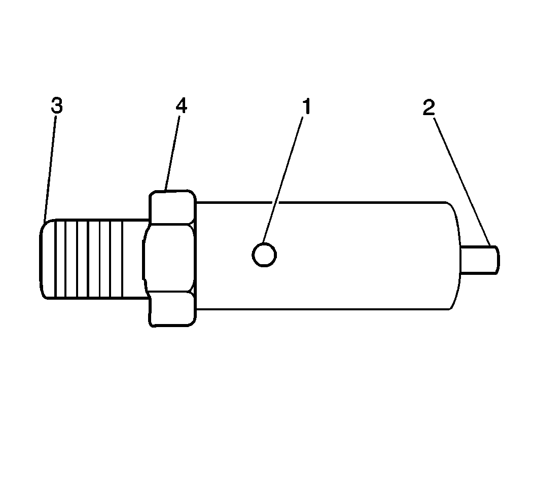
A safety valve is installed in the air supply reservoir in order to stop air pressure buildup beyond a safe limit. The safety valve protects the reservoirs and lines in case of a governor failure. The valve is a spring-loaded type with a ball and seat.
If the air pressure rises to approximately 1034 kPa (150 psi) the ball is forced to unseat. This condition relieves air pressure through the exhaust vent (1) in the spring cage. When the air pressure decreases sufficiently, spring tension seats the ball, sealing the reservoir. The rated air pressure (4) is stamped on one of the wrench flats.
Spring Brake Control Valve
The spring brake control valve is used on all trucks and tractors. The spring brake control valve works with the spring brake relay valve. The valve allows the front brake service lines to modulate the spring brake chambers when rear service air pressure fails.
The valve is mounted directly to the rear frame side rail except on tandem axle vehicles that use a mounting bracket between the valve and side rail. The exhaust port always points down.
The spring brake control valve has the following components:
| • | A supply port connected to the system park valve |
| • | A delivery port to the spring brake relay valve |
| • | A delivery port connected to the spring brake relay valve |
| • | A control port connected to the front circuit on the dual application valve |
| • | A rear reservoir port that senses rear service reservoir pressure |
| • | An exhaust port covered by a diaphragm |
All of the ports are labeled with embossed letters.
The spring brake control valve delivers a set air pressure to the delivery line as long as the supply and reservoir port pressures are 380 kPa (55 psi) or more. This air pressure is called the rated spring hold off pressure. The valve detects an air pressure loss in the rear service reservoir through the reservoir port. When that happens, the front brake service air at the control port of the valve modulates the spring brake chambers with the brake pedal as if they were service brakes. This condition allows the spring brake chambers to work in place of the service brakes during emergency situations.
When the system park valve is pulled out to the park position, the supply port air is exhausted, causing delivery port air to vent through the exhaust port.
