Air Lines and Related Components
The air lines deliver compressed air throughout the vehicle. The air lines are made from copper and nylon tubing. The fittings are as follows:
| • | 4.8 mm (3/16 in) |
| • | 6.4 mm (¼) in |
| • | 9.5 mm (3/8 in) |
| • | 12.7 mm (½ in) diameter push-in type for all nylon air lines |
| • | 19 mm (¾ in) diameter compression fittings for copper air lines |
The nylon air lines are color coded for system identification in the following ways:
| • | Black -- Accessory Equipment |
| • | Blue -- Front System |
| • | Green -- Rear System |
| • | Red -- Parking Brake |
| • | Yellow -- Trailer System |
| • | Blue -- Trailer Supply |
Nylon Air Lines
Notice: Nylon air line should be used to replace existing nylon lines only. Do not route nylon air lines in areas where temperatures could exceed 93°C (200°F). Damage to the nylon lines could occur.
Notice: When replacing air lines connected to the push-in type fittings, be certain that the nylon air line is pushed-in and seated in the fitting. Install the tube into the fitting until no tube color is visible between the gauge band and the fitting. The air line may blow out if the tube is not properly seated in the fitting.
All vehicles equipped with air brakes use a special push-in type fitting. These fittings are serviced as an assembly and should not be taken apart.
Flexible Hoses
Flexible hoses are used at the air brake chambers, between the frame and axles, and the trailer connections. Any chafed, worn, or kinked flexible hoses must be replaced.
Supporting Components
Maintain all air line clips, ties, grommets and supporting brackets to prevent unnecessary vibrations, and the loosening or separation of connections. Check the air line routing and support the components regularly. Do not route the nylon lines near high heat sources such as the exhaust system.
Tabbed air line support brackets are used at some locations. A tab is positioned in a hole in the frame and retained with a single nut and bolt. The tab prevents the bracket from moving.
Use clamps on these brackets for holding the air line and power cable bundles. All clamps and brackets must be in place and tightened securely.
The air line supports support other components. Firmly mount the support in position. Do not allow the air lines to rub on the vehicle components.
The clamps and the band ties support and protect the air lines. Use the band ties to hold clusters of air lines and cables where it is not possible to use clamps, brackets or supports.
Heat Shields and Grommets
Grommets are used when air lines pass through frame members or sheet metal. The grommets prevent wear and cuts on the air lines. Check the grommets each time brake service is required. Components must be in good condition and mounted correctly. The grommets should not be torn or bent. Replace the grommets if they are missing or damaged.
Any heat shields removed during service must be installed to protect the air lines from heat.
Reservoirs
Air reservoirs are the holding tanks for their respective systems. Each service system is a complete and separate air system. The service reservoirs isolate the front and the rear air brake systems. A front axle service reservoir stores compressed air for the front brakes. The rear service reservoirs store compressed air for the rear brakes. There is often more than one rear service reservoir. An in-line check valve at the inlet to each service reservoir prevents an air pressure loss from the service brakes if there is a leak in the supply air reservoir or the compressor discharge line. The service reservoirs are sometimes called dry tanks. The operator controls the air flow in both systems through a dual application valve.
The air supply reservoir holds heated air from the air compressor. As the air cools, water and contaminants collect in the supply reservoir. Drain this water at least once a day, unless the vehicle is equipped with an optional reservoir drain valve (automatic type).
Dual Air Pressure Gauge

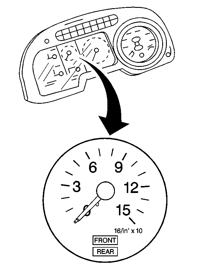
The dual air pressure gauge located in the instrument panel indicates the front and rear service system air pressures. Do not drive the vehicle when the front or rear gauge readings are below 450 kPa (65 psi). Check the dual air pressure gauge regularly with an accurate test gauge. Replace the dual air pressure gauge when the pressure reading varies by more than 27 kPa (4 psi), and there are no air leaks in the dual air pressure gauge circuit.
The dual air pressure gauge has two needles in contrasting colors. These needles show the front axle service and the rear axle service brake system air pressure. The dual air pressure gauge dial is marked from 0 to 15. Multiply the reading by 10 for the amount of psi.
The air pressure from the front and rear air brake systems is brought to the dual air pressure gauge through two nylon air lines. The two nylon air lines are routed from the instrument panel, through the floor, to the dual application valve. Inside the dual air pressure gauge, each nylon air line connects to a flattened, curved tube that straightens under internal pressure. The indicator needles are linked to the tubes and react to movement to indicate the air pressure.
Low Air Pressure Switch
The low air pressure switch is an air-controlled electrical switch that controls a cab tone alarm and warning light.
The low air pressure switch has a nominal pressure setting of 470 to 510 kPa (68 to 74 psi). If the low air pressure switch fails, replace the switch.
