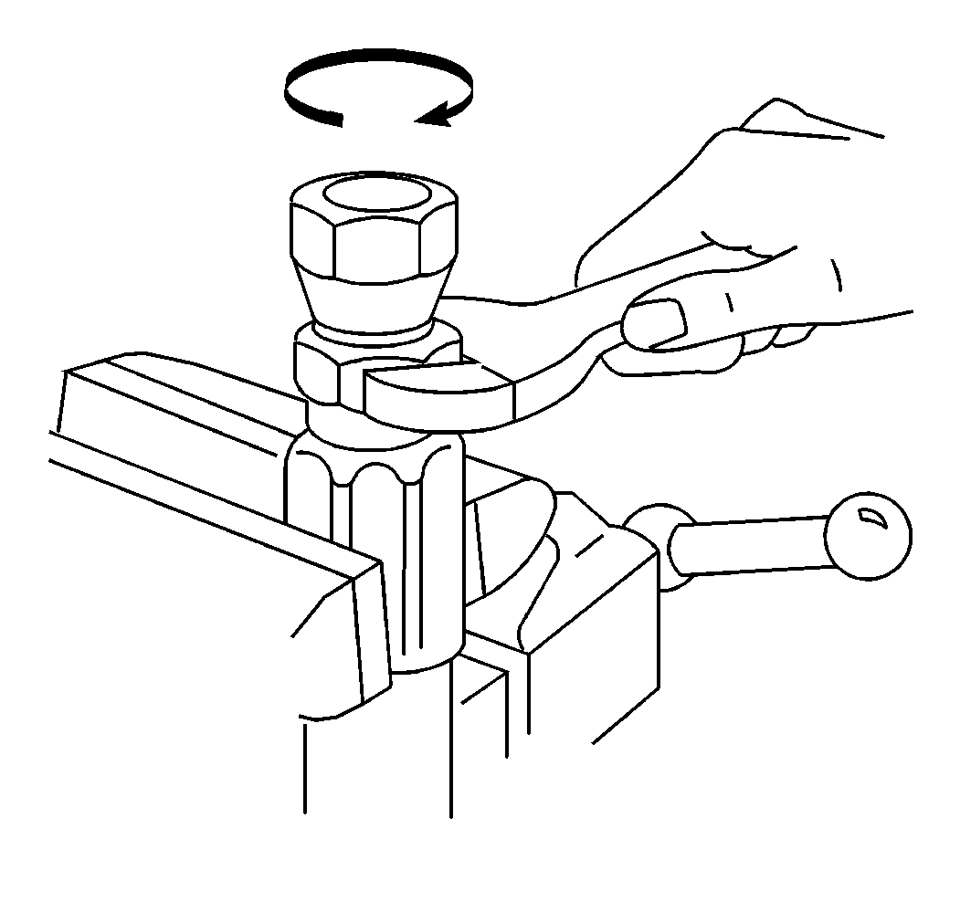
Hose and Line Replacement Nylon and Metal Compression
Removal Procedure
- Apply the parking brake.
- Block the wheels.
- Remove the exhaust air from the lines. Refer to Draining Reservoirs
- Remove the clips or the tubing clamps.
- Remove the air line.
- Remove the tube nuts from each fitting.
- Remove the compression ring from the tube.
- Clean the fittings and the tube nuts with a clean cloth.
- Inspect the fittings and the tube nuts for nicks, burrs, and wear spots. Replace the fittings as needed.
- Cut the tube squarely at each end the same length as the old tube. Shape the metal tube to match the old one.
- Assemble the tube nut on the new tube.
- Assemble the compression ring on the tube.
- Assemble the fitting and the tube.
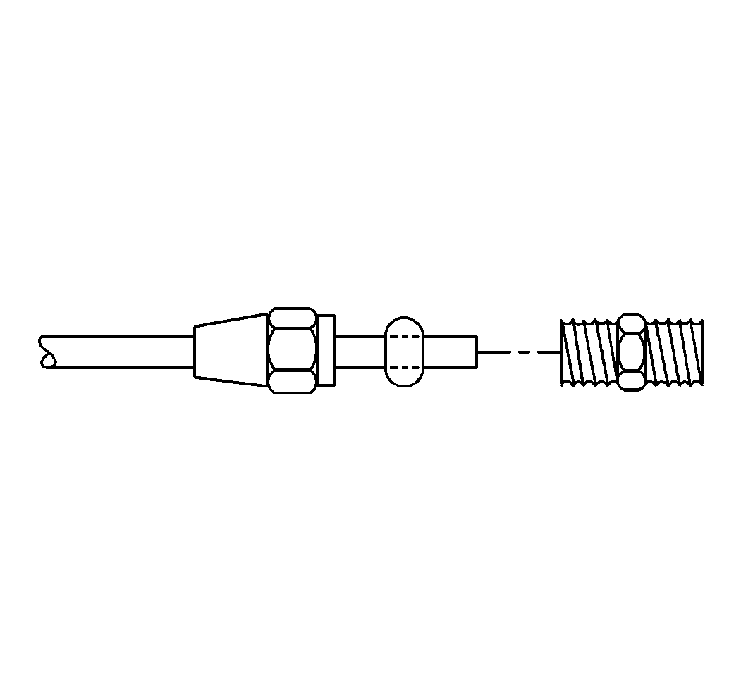
Notice: When replacing tubing, make sure that the tubing is free of burrs, cuttings, and dirt. While wearing safety glasses, use compressed air to blow out contaminants. Contaminants can destroy the air brake valve sealants.
Notice: Nylon air line should be used to replace existing nylon lines only. Do not route nylon air lines in areas where temperatures could exceed 93°C (200°F). Damage to the nylon lines could occur.
Important: Do not use flared-type fittings in the air brake system. When replacing the air lines, use the end fitting kits to make new air line assemblies. Special tools are not required.
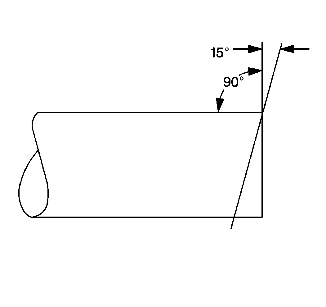
Important: Check that the tubing is completely inserted into the fitting.
Installation Procedure
- Install the air line.
- Install the clips or the tubing clamps.
- Start the engine.
- Charge the system air pressure to the governor cut-out point.
- Stop the engine.
- Check for leaks using a soap solution.
- Check for proper brake operation.
- Remove the wheel blocks.

Leaks are not permissible.
Hose and Line Replacement Nylon Push-In Type Fitting
Removal Procedure
- Apply the parking brake.
- Block the wheels.
- Remove the exhaust air from the lines. Refer to Draining Reservoirs
- Remove the clips or the tubing clamps as needed.
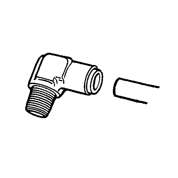
- Remove the nylon tube from the fitting without using tools.
- Push the nylon tube into the fitting until the tube bottoms on the tube stop.
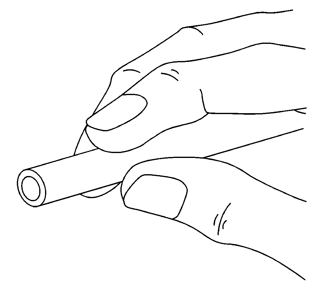
- Depress the collet.
- Remove the tube from the fitting while the collet is depressed.
- Inspect the fitting for nicks, burrs, and wear spots. Replace the fittings as needed.
- Cut the nylon tube with a sharp tube cutter.
- Check that the nylon tube is cut square and is free of burrs.
- Assemble the nylon tube into the fitting. Push the tube firmly into the fitting until the tube bottoms on the tube stop.
Notice: Nylon air line should be used to replace existing nylon lines only. Do not route nylon air lines in areas where temperatures could exceed 93°C (200°F). Damage to the nylon lines could occur.
Notice: When replacing air lines connected to the push-in type fittings, be certain that the nylon air line is pushed-in and seated in the fitting. Install the tube into the fitting until no tube color is visible between the gauge band and the fitting. The air line may blow out if the tube is not properly seated in the fitting.
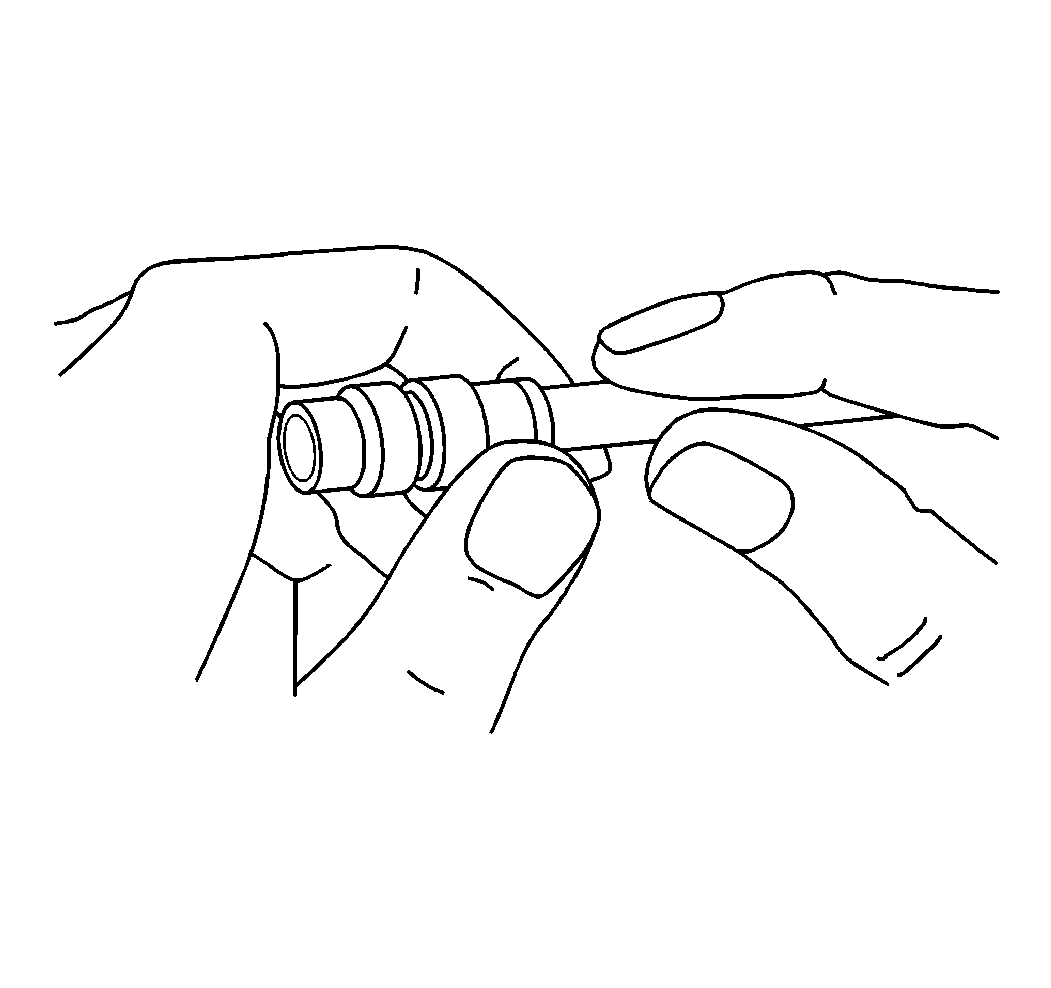
Important: Once removed, the nylon tube can be reinserted up to five times before it must be replaced.

Installation Procedure
- Place the tape around the air line to bundle the air line with the other air lines.
- Start the engine.
- Charge the system air pressure to the governor cut-out point.
- Stop the engine.
- Check for leaks with a soap solution around the fittings.
- Check for the proper brake operation.
- Remove the wheel blocks.

Leakage is not permissible.
Hose and Line Replacement Flexible Hose
Removal Procedure
- Apply the parking brake.
- Block the wheels.
- Exhaust the air from the lines. Refer to Draining Reservoirs .
- Remove the air line.
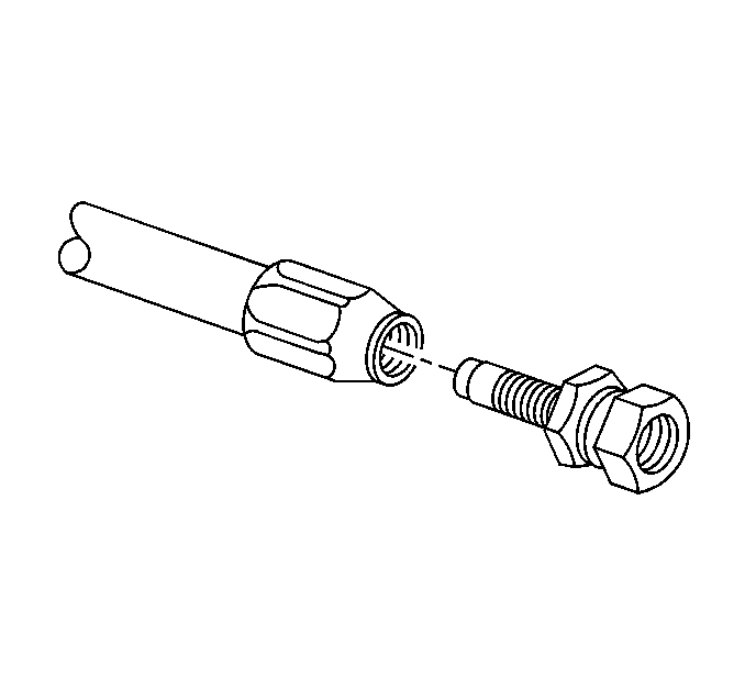
- Unscrew the nipple from the socket and the flexible hose.
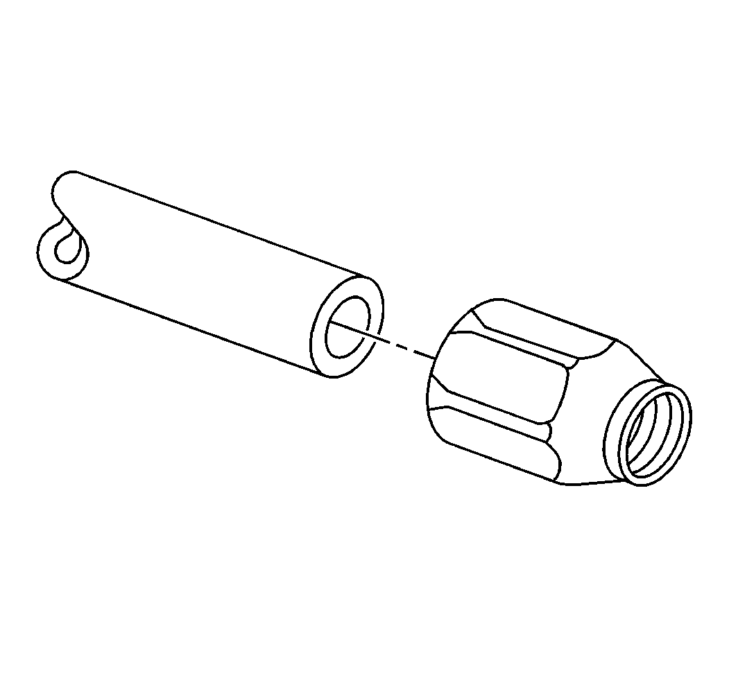
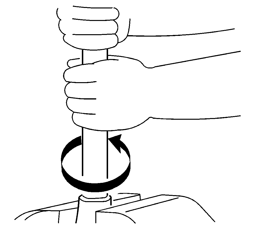
- Disassemble the flexible hose. Turn the hose clockwise in order to unscrew the hose from the socket.
- Clean the nipple and the socket with a clean cloth.
- Inspect the nipple and the socket for the following conditions:
- Replace any damaged components.
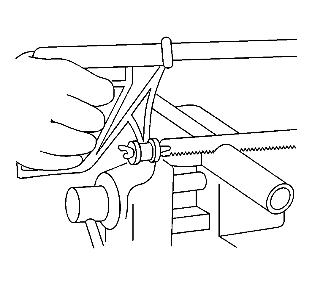
- Use a fine tooth hacksaw or cutting wheel in order to cut the flexible hose squares the same length as the original part.
- Assemble the flexible hose into the socket. Turn the hose counterclockwise in the socket until it bottoms; then back off the flexible hose ¼ turn.
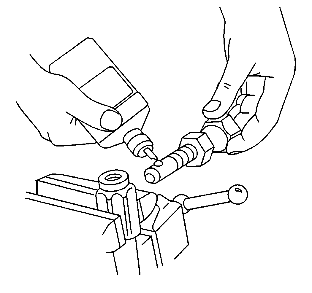
- Lubricate the nipple threads with clean engine oil.
- Assemble the nipple.
- Tighten the nipple.
| • | Nicks |
| • | Burrs |
| • | Wear Spots |
Notice: Use the correct fastener in the correct location. Replacement fasteners must be the correct part number for that application. Fasteners requiring replacement or fasteners requiring the use of thread locking compound or sealant are identified in the service procedure. Do not use paints, lubricants, or corrosion inhibitors on fasteners or fastener joint surfaces unless specified. These coatings affect fastener torque and joint clamping force and may damage the fastener. Use the correct tightening sequence and specifications when installing fasteners in order to avoid damage to parts and systems.
Tighten
Tighten the nipple, leaving a 0.8 mm (0.03 in) clearance between
the nipple hex and the socket.
Installation Procedure
- Install the air line.
- Start the engine.
- Charge the system air pressure to the governor cut-out point.
- Check for leaks with a soap solution. No leakage is permissible.
- Test the brakes for proper operation.
- Remove the wheel blocks.
