Disassembly Procedure
Tools Required
| • | J 42882 Adjuster Nut Socket |
| • | J 6222-A Shaft Seal Protector |
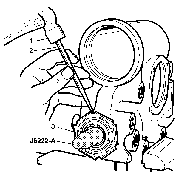
- Remove the coupling shield retainer and lock nut (3) from the adjuster nut assembly using a drift (2) and a hammer (1).
- Place J 6222-A over the end of the stub shaft.
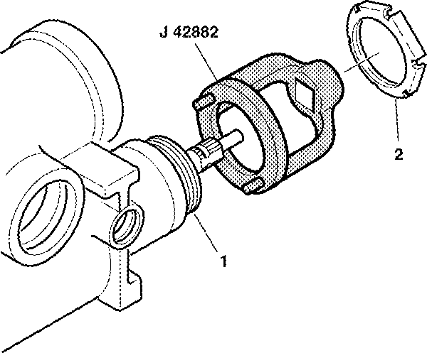
- Remove the adjuster nut assembly (1) from the steering gear housing using J 42882 .
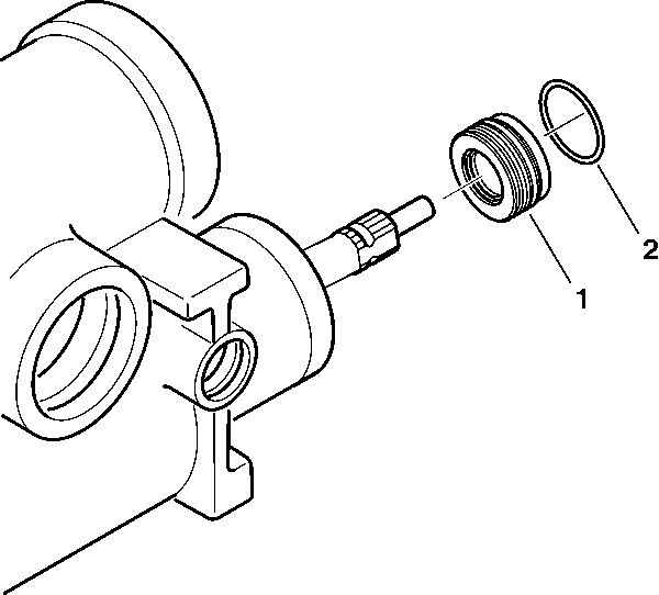
- Remove the thrust support assembly (1) from the steering gear housing.
- Remove the O-ring seal (2).


Assembly Procedure
Tools Required
J 42882 Adjuster Nut Socket
- Lubricate the new O-ring seal (2).
- Install the new O-ring seal (2).
- Install the thrust support assembly (1).
- Connect the adjuster nut assembly (1) to the steering gear housing using J 42882 .
- Install the coupling shield retainer and lock nut (2) to the adjuster nut assembly (1).
- To adjust the thrust bearing preload; refer to Valve Housing and Input Shaft Assemble .
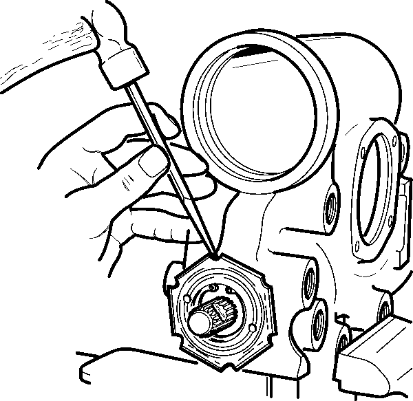
- Using a drift in a notch, install the coupling shield retainer and lock nut.
- Hold the adjuster nut assembly in order to maintain alignment of the marks while tightening the coupling shield retainer and lock nut.
- Tighten the coupling shield retainer and lock nut securely.

Important: Install a new O-ring seal each time the thrust support assembly is removed from the steering gear.

Notice: Use the correct fastener in the correct location. Replacement fasteners must be the correct part number for that application. Fasteners requiring replacement or fasteners requiring the use of thread locking compound or sealant are identified in the service procedure. Do not use paints, lubricants, or corrosion inhibitors on fasteners or fastener joint surfaces unless specified. These coatings affect fastener torque and joint clamping force and may damage the fastener. Use the correct tightening sequence and specifications when installing fasteners in order to avoid damage to parts and systems.
Tighten
Tighten the adjuster nut assembly (1) to 28.5-31.2 N·m
(21-23 lb ft) and back off 15 degrees-25 degrees.

