For 1990-2009 cars only
Disassembly Procedure
Tools Required
| • | J 38639 Steering Column Housing Bearing Installer |
| • | J 8092 Driver Handle |
| • | J 22635 Lock Shoe and Release Lever Pin Remover and Installer |
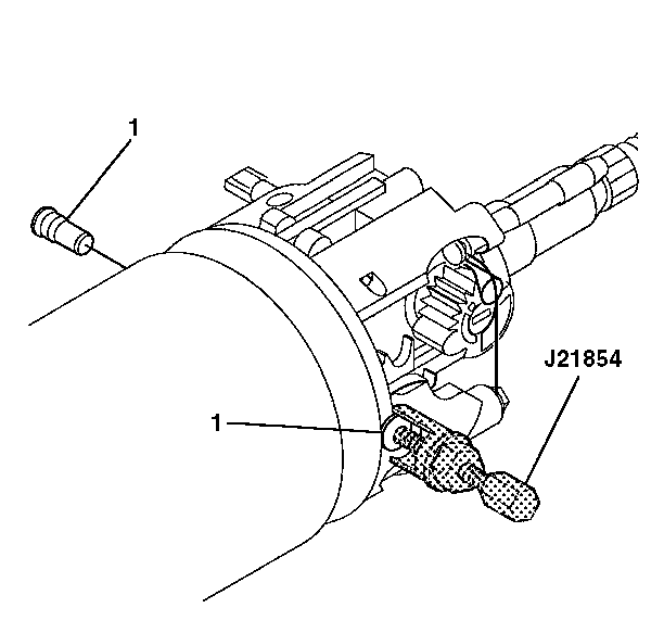
| • | J 21854-01 Pivot Pin Remover |
- Remove the pivot and pulse switch assembly. Refer to Pivot and Pulse Switch Assembly - Off Vehicle .
- Install the tilt lever. Refer to Tilt Lever Replacement - On Vehicle .
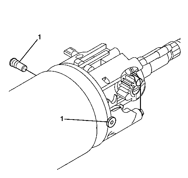
- Remove 2 pivot pins (1) using J 21854-01 .
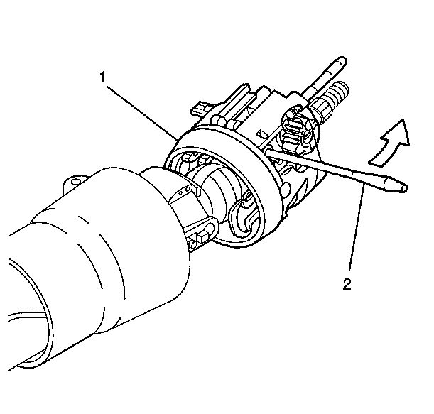
- Pull back on the tilt lever (2) and pull the steering column housing assembly (1) down and away from the steering column.
- Remove the tilt lever (2). Refer to Tilt Lever Replacement - On Vehicle .
- Disassemble the steering column housing assembly, if needed:
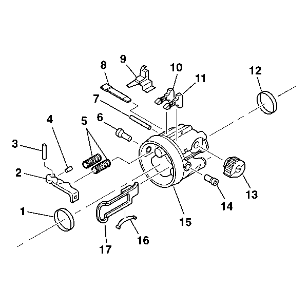
| 6.1. | Remove the bearing assembly (12). |
| 6.2. | Remove the wire protector shield (9). |
| 6.3. | Remove the switch actuator rack (17) and the rack preload spring (16). |
| 6.4. | Remove the drive shaft (8). |
| 6.5. | Remove the switch actuator sector (13). |
| 6.6. | Release the lever pin (3) using J 22635 . |
| 6.7. | Remove the shoe release lever (2). |
| 6.8. | Remove the release lever spring (4). |
| 6.9. | Remove the dowel pin (7). |
| 6.10. | Remove the steering wheel lock shoes (10) and (11) using J 22635 and the shoe springs (5). |
| 6.11. | Remove the bearing assembly (1). |
Assembly Procedure
Tools Required
| • | J 38639 Steering Column Housing Bearing Installer |
| • | J 8092 Driver Handle |
| • | J 22635 Lock Shoe and Release Lever Pin Remover and Installer |
| • | J 21854-01 Pivot Pin Remover |
- To assemble the steering column housing assembly if needed:
- Install the bearing assembly (1)
- Install the shoe springs (5).
- Install the steering wheel lock shoes (10) and (11).
- Install the dowel pin (7).
- Install the release lever spring (4).
- Install the shoe release lever (2).
- Install the lever pin (3) using J 22635 .
- Install the drive shaft (8).
- Install the switch actuator sector (13).
- Install the rack preload spring (16).
- Install the switch actuator rack (17) to the switch actuator sector (13).
- Install the bearing assembly (12) using J 8092 and J 38639 .
- Install the wire protector shield (9).
- Stake the steering column housing assembly in 3 places.
- Install the steering column housing assembly:
- Install 2 pivot pins (1).
- Press the 2 pins (1) until they are firmly seated.
- Install the pivot and pulse switch assembly. Refer to Pivot and Pulse Switch Assembly - Off Vehicle .

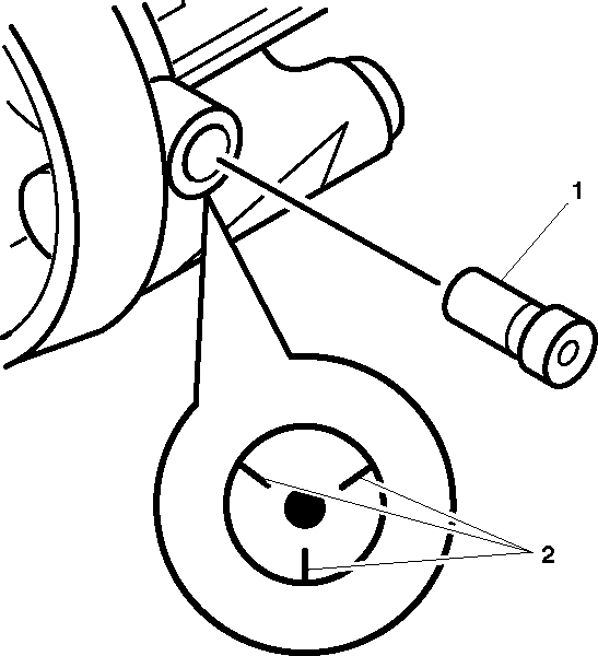
Important: If the steering column housing assembly has been staked 3 times it must be replaced.

| 16.1. | Install the tilt lever (2). Refer to Tilt Lever Replacement - On Vehicle . |
| 16.2. | Position the steering column housing assembly (1) onto the steering column housing support. |
| 16.3. | Align the switch actuator rack with the pin on the end of the ignition switch actuator assembly. |
| 16.4. | Pull back on the tilt lever (2) to position the steering column housing assembly (1). |
| 16.5. | Push the steering column housing assembly (1) into the steering column housing support . |
| 16.6. | Release the tilt lever (2) to lock the steering wheel lock shoes and the dowel pin. |
| 16.7. | Remove the tilt lever (2). Refer to Tilt Lever Replacement - On Vehicle . |
