Wheel Installation Disc Type - Single Front/Rear
- If the vehicle is equipped with hub-piloted wheels, use a brush in order to apply a thin coat of Frey Lube II® lubricant or equivalent to the hub pads only.
- If the vehicle is equipped with hub-piloted wheels, turn the hub so that a hub pad is at a 12 o'clock position.
- Install the wheel on the hub.
- For 8-hole aluminum or steel hub-piloted wheels, install the wheel nuts.
- Tighten the wheel nut to 100 N·m (74 lb ft) in the sequence shown.
- Tighten the wheel nut to 550 N·m (400 lb ft) in the sequence shown.
- For 10-hole aluminum or steel hub-piloted wheels, install the wheel nuts.
- Tighten the wheel nut to 225 N·m (166 lb ft) in the sequence shown.
- Tighten the wheel nut to 644 N·m (475 lb ft) in the sequence shown.
- For 10-hole aluminum stud-piloted wheels, install the wheel nuts.
- Tighten the wheel nut to 225 N·m (166 lb ft) in the sequence shown.
- Tighten the wheel nut to 644 N·m (475 lb ft) in the sequence shown.
- For 10-hole steel stud-piloted wheels, install the wheel nuts.
- Tighten the wheel nut to 225 N·m (166 lb ft) in the sequence shown.
- Tighten the wheel nut to 650 N·m (480 lb ft) in the sequence shown.
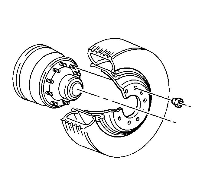
Notice: Wheel hub flanges, wheel studs, and stud nuts should be free of rust, lubricants, dirt, and finish color paint on all contact surfaces to ensure proper torque retention.
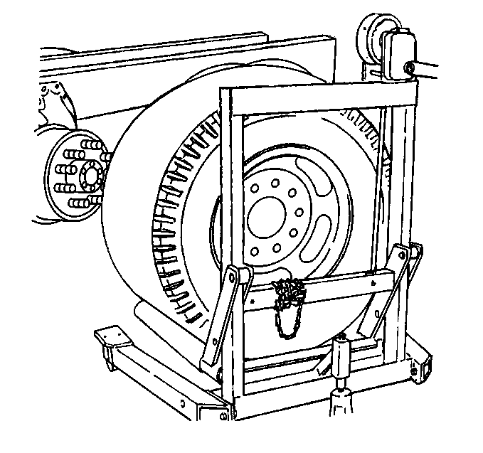

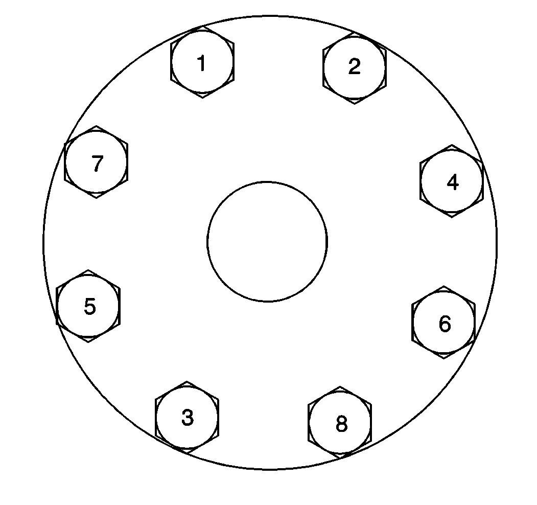
Important: Tighten the wheel nuts progressively using the first specification; then retighten the nuts using the second specification.
Notice: Use the correct fastener in the correct location. Replacement fasteners must be the correct part number for that application. Fasteners requiring replacement or fasteners requiring the use of thread locking compound or sealant are identified in the service procedure. Do not use paints, lubricants, or corrosion inhibitors on fasteners or fastener joint surfaces unless specified. These coatings affect fastener torque and joint clamping force and may damage the fastener. Use the correct tightening sequence and specifications when installing fasteners in order to avoid damage to parts and systems.
Tighten
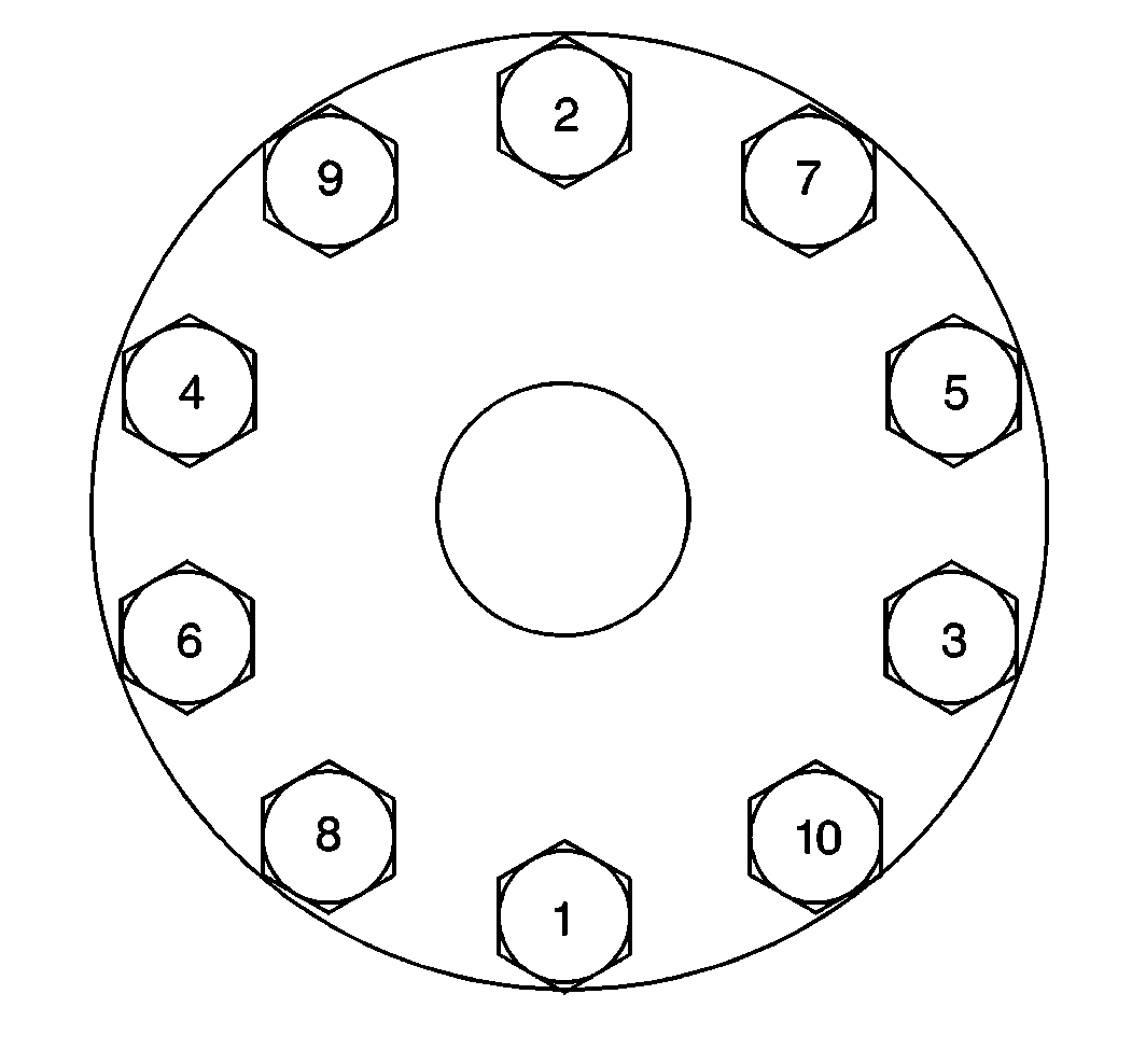
Important: Tighten the wheel nuts progressively using the first specification; then retighten the nuts using the second specification.
Tighten
Tighten
Tighten
Wheel Installation Disc Type - Dual/Rear
- If the vehicle is equipped with hub-piloted wheels, use a brush in order to apply a thin coat of Frey Lube II® lubricant or equivalent to the hub pads only.
- If the vehicle is equipped with hub-piloted wheels, turn the hub so that a hub pad is at a 12 o'clock position.
- Install the inner wheel if you removed the inner wheel.
- Torque the inner stud nuts.
- For 10-hole aluminum stud-piloted wheels, install the wheel nuts.
- Tighten the stud nut to 225 N·m (166 lb ft) in the sequence shown.
- Tighten the stud nut to 644 N·m (475 lb ft) in the sequence shown.
- For 10-hole steel stud-piloted wheels, install the wheel nuts.
- Tighten the stud nut to 225 N·m (166 lb ft) in the sequence shown.
- Tighten the stud nut to 800 N·m (590 lb ft) in the sequence shown.
- Install the outer wheel on the hub. Oppose the valve stems of both wheels by 180 degrees.
- For eight-hole wheels, install the wheel nuts.
- Tighten the stud nut to 100 N·m (74 lb ft) in the sequence shown.
- Tighten the stud nut to 550 N·m (400 lb ft) in the sequence shown.
- Tighten the stud nut to 225 N·m (166 lb ft) in the sequence shown.
- Tighten the stud nut to 644 N·m (475 lb ft) in the sequence shown.
- For ten-hole aluminum stud-piloted wheels, install the wheel nuts.
- Tighten the stud nut to 225 N·m (166 lb ft) in the sequence shown.
- Tighten the stud nut to 644 N·m (475 lb ft) in the sequence shown.
- For ten-hole steel stud-piloted wheels, install the wheel nuts.
- Tighten the stud nut to 225 N·m (166 lb ft) in the sequence shown.
- Tighten the stud nut to 800 N·m (590 lb ft) in the sequence shown.
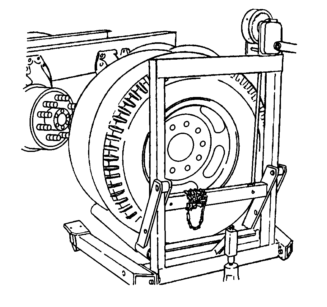
Notice: Wheel hub flanges, wheel studs, and stud nuts should be free of rust, lubricants, dirt, and finish color paint on all contact surfaces to ensure proper torque retention.
Notice: Stud-piloted hubs' inner and outer stud nuts used on the right side of the vehicle have right-hand threads. Inner and outer nuts are stamped with the letter L to signify left or R to signify right. Care should be exercised to prevent trying to use the wrong thread nut as damage to the stud threads could occur.
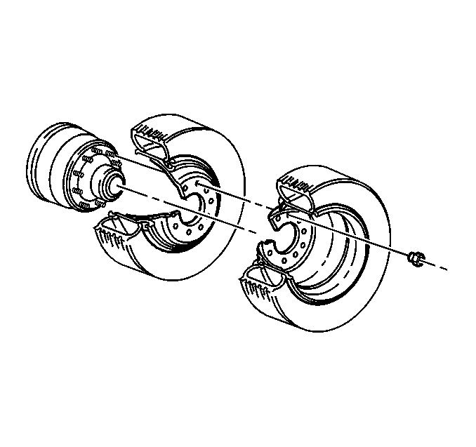

Notice: When only the outer wheel was removed, the inner wheel stud nuts must be torqued prior to the installation of the outer wheel. Failure to retorque inner wheel stud nuts can cause wheel damage.
Important: For vehicles equipped with stud-piloted wheels, tighten the wheel nuts progressively using the first specification; then retighten the nuts using the second specification.
Notice: Use the correct fastener in the correct location. Replacement fasteners must be the correct part number for that application. Fasteners requiring replacement or fasteners requiring the use of thread locking compound or sealant are identified in the service procedure. Do not use paints, lubricants, or corrosion inhibitors on fasteners or fastener joint surfaces unless specified. These coatings affect fastener torque and joint clamping force and may damage the fastener. Use the correct tightening sequence and specifications when installing fasteners in order to avoid damage to parts and systems.
Tighten
Tighten

Notice: Stud-piloted hubs' inner and outer stud nuts used on the right side of the vehicle have right-hand threads. Inner and outer nuts are stamped with the letter L to signify left or R to signify right. Care should be exercised to prevent trying to use the wrong thread nut as damage to the stud threads could occur.
Tighten

Notice: Stud-piloted hubs' inner and outer stud nuts used on the right side of the vehicle have right-hand threads. Inner and outer nuts are stamped with the letter L to signify left or R to signify right. Care should be exercised to prevent trying to use the wrong thread nut as damage to the stud threads could occur.
Tighten
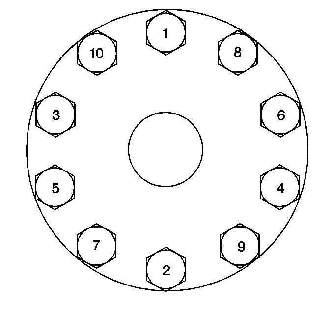
Notice: Stud-piloted hubs' inner and outer stud nuts used on the right side of the vehicle have right-hand threads. Inner and outer nuts are stamped with the letter L to signify left or R to signify right. Care should be exercised to prevent trying to use the wrong thread nut as damage to the stud threads could occur.
Tighten
Tighten
Wheel Installation Cast Type - Single Front/Rear
- Install the wheel.
- Position the rim clamps properly. Install the rim clamps.
- Install the wheel nuts to finger tightness.
- Tighten the wheel nuts in the sequence shown until the nuts are snug.
- Tighten the wheel nuts to 271 N·m (200 lb ft) in the sequence shown.
- Inspect for wheel runout.
- If necessary, adjust the excess runout by loosening the nuts on the side where the variation or runout is the greatest.
- Tighten the opposite wheel nut until that nut is snug.
- When the tire runs true, tighten all of the wheel nuts to 271 N·m (200 lb ft) in the sequence shown.
Caution: When the vehicle, wheels, or fasteners are new, tighten inner stud nuts and/or rim clamp nuts with as torque wrench at 160, 300 and 1600 kilometers (100, 500 and 1,000 miles). The clamping system used on these wheels, in some cases, needs to seat before the fasteners will hold a uniform clamp load and remain fully tightened. Nut tightness on all wheels should be set with a torque wrench every 1600 kilometers (1,000 miles).
Tighten all wheel stud nuts and/or rim clamp nuts with a torque wrench after installing any wheel. Use the correct torque listed for the type of wheels as shown in the procedures which follow. Wheel nuts should be tightened alternately and evenly to the correct torque in the sequence shown. Never use oil or grease on studs or nuts. Improperly tightened wheel nuts could eventually allow the wheel to come off while the vehicle is moving, causing loss of control and personal injury.Notice: Wheel hub flanges, wheel studs, and stud nuts should be free of rust, lubricants, dirt, and finish color paint on all contact surfaces to ensure proper torque retention.
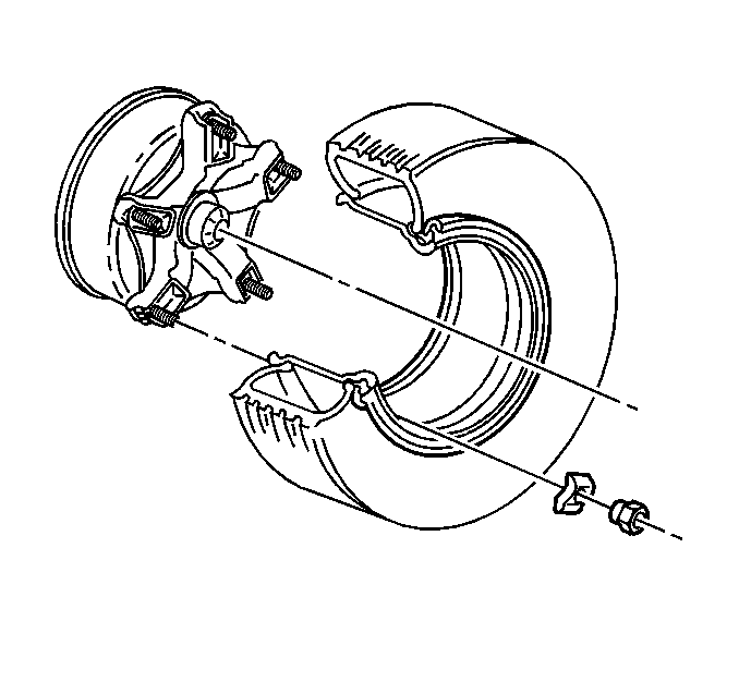
Notice: Do not tighten a nut with the rim clamp in a cocked position. This could cause rim damage or runout (wheel wobble).
Notice: Use the correct fastener in the correct location. Replacement fasteners must be the correct part number for that application. Fasteners requiring replacement or fasteners requiring the use of thread locking compound or sealant are identified in the service procedure. Do not use paints, lubricants, or corrosion inhibitors on fasteners or fastener joint surfaces unless specified. These coatings affect fastener torque and joint clamping force and may damage the fastener. Use the correct tightening sequence and specifications when installing fasteners in order to avoid damage to parts and systems.
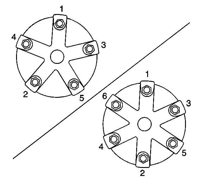
Tighten
Tighten
Wheel Installation Cast Type - Dual/Rear
- Install the spacer over the wheel.
- Do not cock the wheel spacer.
- Install the clamps
- Install the wheel nuts to finger tightness.
- Tighten the wheel nuts in the sequence shown until the nuts are snug.
- Tighten the wheel nuts to 271 N·m (200 lb ft) in the sequence shown.
- Inspect the clamps, verifying that the clamps do not bottom out.
- Inspect the rim edges, verifying that the edges do not meet the spacer band.
- Inspect for wheel runout.
- If necessary, adjust the excess runout by loosening the nuts on the side where the variation or runout is the greatest.
- Tighten the opposite wheel nut until that nut is snug.
- When the tire runs true, tighten all of the wheel nuts to 271 N·m (200 lb ft) in the sequence shown.

| • | Fit the wheel spacer snugly to the spokes and against the inside of the rim gutter edge. |
| • | Inspect for roundness by turning the wheel spacer on the wheel. |
| • | Install the outer rim with the valve stem as close to 180 degrees from the inner rim valve stem as possible. |
| • | Fit the wheel spacer snugly to the spokes and against the inside the rim gutter edge. |
| • | Inspect for roundness by turning the wheel spacer on the wheel. |
| • | Install the outer rim with the valve stem as close to 180 degrees from the inner rim valve stem as possible. |

Notice: Use the correct fastener in the correct location. Replacement fasteners must be the correct part number for that application. Fasteners requiring replacement or fasteners requiring the use of thread locking compound or sealant are identified in the service procedure. Do not use paints, lubricants, or corrosion inhibitors on fasteners or fastener joint surfaces unless specified. These coatings affect fastener torque and joint clamping force and may damage the fastener. Use the correct tightening sequence and specifications when installing fasteners in order to avoid damage to parts and systems.
Tighten
Tighten
