Water Pump Replacement LG5
Removal Procedure
- Remove the front wheelhouse panel.
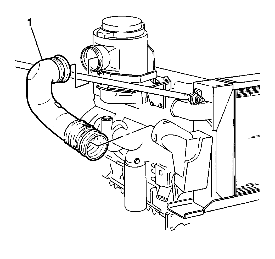
- Remove the front intake air duct (1) from the air filter housing.
- Drain the coolant. Refer to Cooling System Draining and Filling .
- Remove the cooling fan. Refer to Fan Replacement .
- Remove the fan drive belt. Refer to Drive Belt Replacement in Engine Mechanical.
- Remove the fan drive belt tensioner. Refer to Drive Belt Tensioner Replacement in Engine Mechanical.
- Remove the fan pulley bracket.
- Remove the generator mounting bracket. Refer to Generator Bracket Replacement in Engine Electrical.
- Remove the lower radiator hose. Refer to Radiator Hose Replacement .
- Remove the bypass hose clamps.
- Remove the bypass hose.
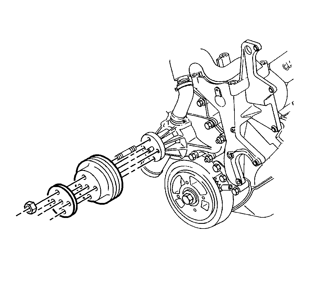
- Remove the water pump pulley and the mounting plate.
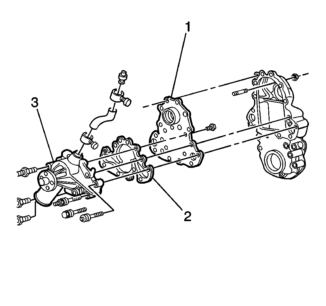
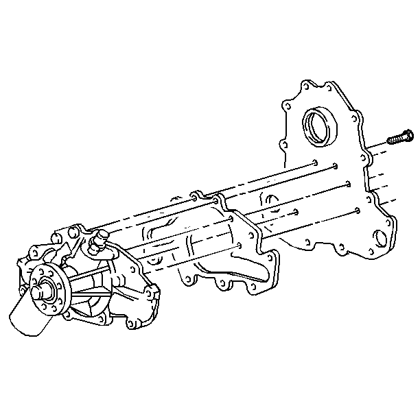
- Remove the water pump backing plate-to-engine (1) front cover studs.
- Remove the water pump-to-engine front cover bolts.
- Remove the water pump (3) from the engine.
- Remove the water pump backing plate-to-water pump bolts.
- Remove the water pump (3) and the gaskets (2).
- Clean the following components in order to remove the old gasket:
- Clean the bolt threads.
- Inspect the following components for wear, deterioration or corrosion. Replace the components as necessary.
| • | The surface of the water pump |
| • | The water pump backing plate |
| • | The engine front cover |
| • | The water pump backing plate |
| • | The engine front cover |
| • | The clamps |
| • | The hoses |
| • | The belts |
| • | The pulleys |
Installation Procedure
- Install the water pump and the gasket to the water pump backing plate.
- Install the water pump backing plate-to-water pump bolts.
- Install the water pump (3) and the gasket (2) to the engine
- Install the water pump-to-engine front cover bolts.
- Install the water pump backing plate-to-engine front cover studs.
- Install the water pump pulley plate and the pulley to the water pump.
- Install the bypass hose.
- Install the bypass clamps.
- Install the lower radiator hose. Refer to Radiator Hose Replacement .
- Install the generator mounting bracket. Refer to Generator Bracket Replacement in Engine Electrical.
- Install the fan pulley bracket.
- Install the fan drive belt tensioner. Refer to Drive Belt Tensioner Replacement in Engine Mechanical.
- Install the fan drive belt. Refer to Drive Belt Replacement in Engine Mechanical.
- Install the cooling fan. Refer to Fan Replacement .
- Install the front intake air duct (1) to the air filter housing.
- Install the front wheelhouse panel.
- Fill the cooling system. Refer to Cooling System Draining and Filling .
- Inspect the system for leaks.

Notice: Use the correct fastener in the correct location. Replacement fasteners must be the correct part number for that application. Fasteners requiring replacement or fasteners requiring the use of thread locking compound or sealant are identified in the service procedure. Do not use paints, lubricants, or corrosion inhibitors on fasteners or fastener joint surfaces unless specified. These coatings affect fastener torque and joint clamping force and may damage the fastener. Use the correct tightening sequence and specifications when installing fasteners in order to avoid damage to parts and systems.
Tighten
Tighten the water pump backing plate-to-water pump bolts to 28 N·m
(21 lb ft).
Tighten
Tighten the water pump-to-engine front cover bolts to 42 N·m
(31 lb ft).
Tighten
Tighten the water pump backing plate-to-engine front cover studs to
23 N·m (17 lb ft).

Tighten
Tighten the water pump pulley bolts to 23 N·m (17 lb ft).


Water Pump Replacement LP4/L21
Removal Procedure
Refer to the Caterpillar® 3126 Unit Repair Manual for information on replacement of the diesel engine water pumps.
- Remove the left front wheelhouse panel.
- Drain the coolant. Refer to Cooling System Draining and Filling .
- Remove the fan assembly. Refer to Fan Replacement .
- Remove the drive belts.
- Remove the pulleys.
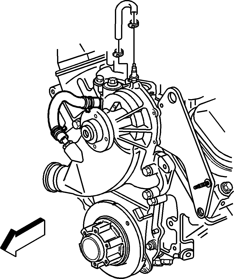
- Loosen the engine coolant air bleed hose clamps.
- Remove the engine coolant air bleed hose and clamps.
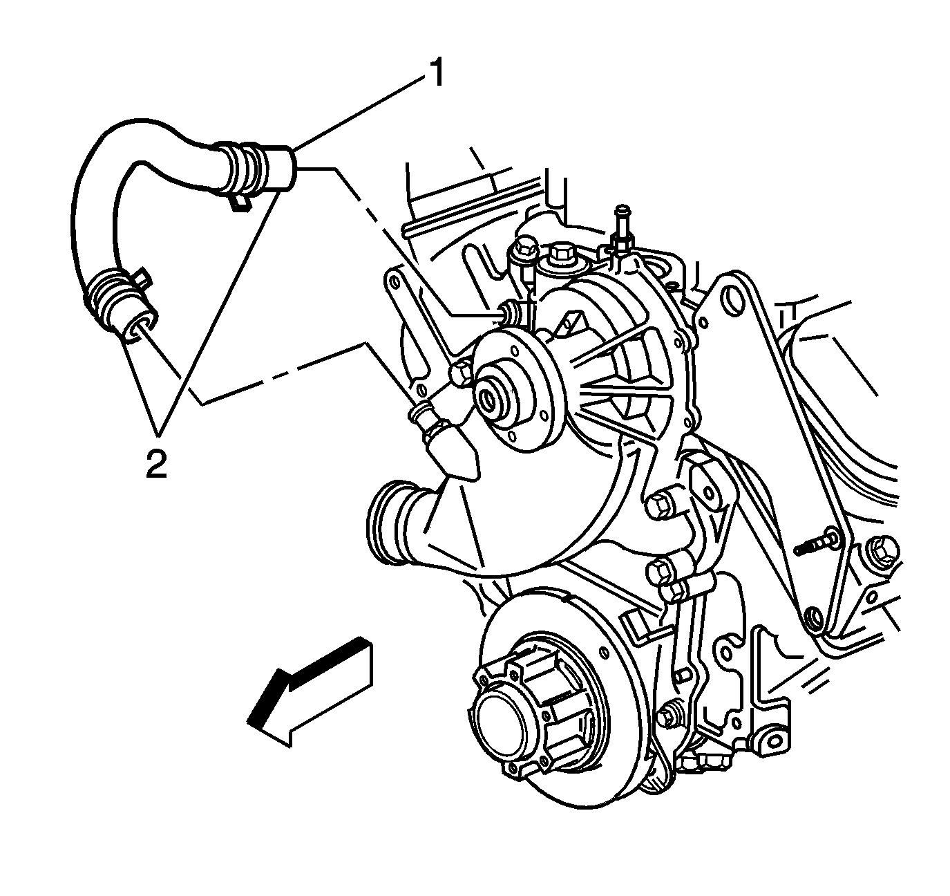
- Loosen the thermostat bypass hose clamps (2).
- Remove the thermostat bypass hose (1) and clamps (2).
- Disconnect the lower radiator hose.
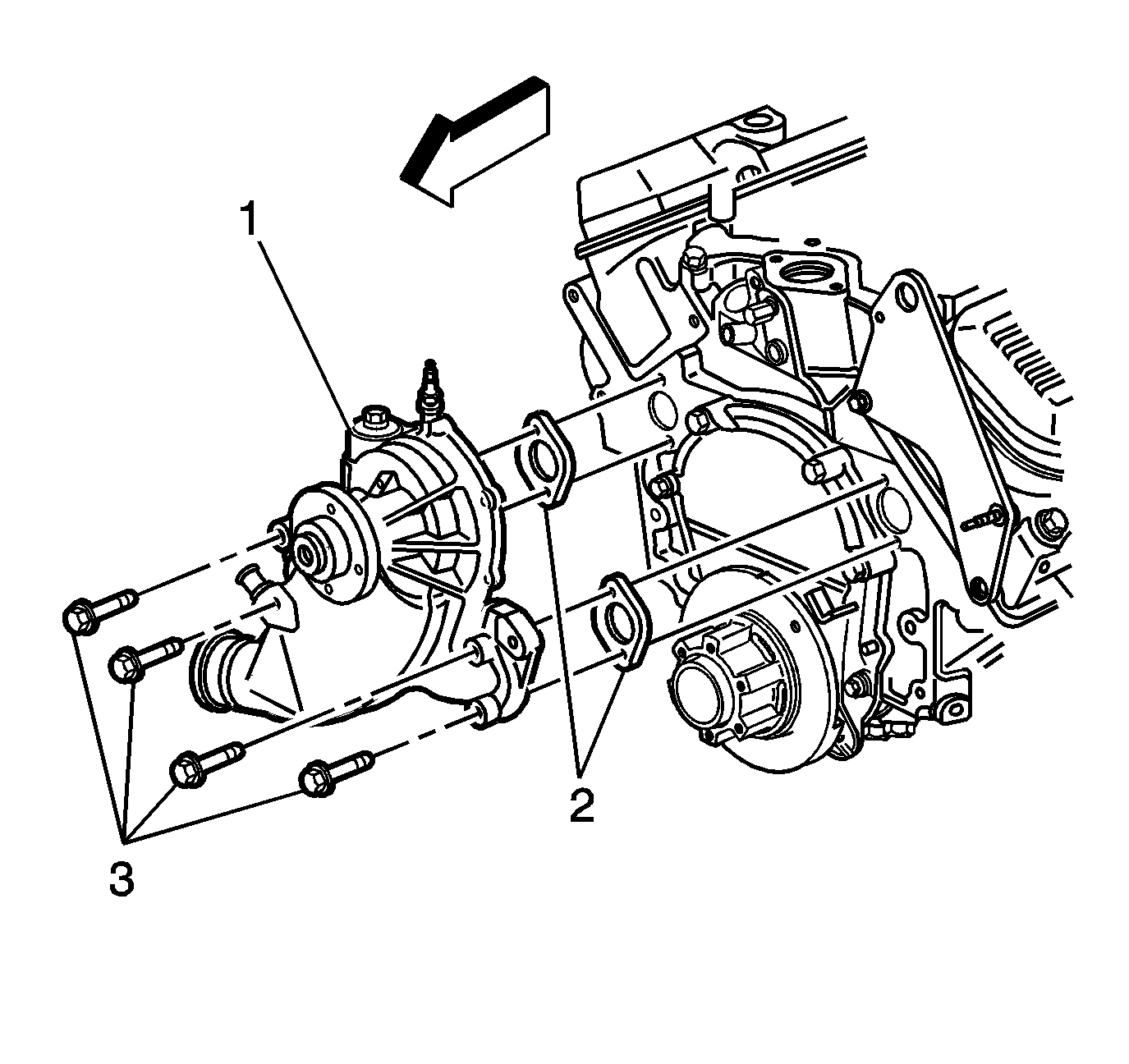
- Remove the water pump bolts (3).
- Remove the water pump (1).
- Remove the water pump gaskets (2).
Installation Procedure
- Install water pump gaskets (2).
- Install the water pump (1).
- Install the water pump bolts (3).
- Connect the lower radiator hose.
- Install the thermostat bypass hose (1) and clamps (2).
- Install the pulleys.
- Install the drive belts.
- Install the fan assembly. Refer to Fan Replacement .
- Install the engine coolant air bleed hose and clamps.

Notice: Use the correct fastener in the correct location. Replacement fasteners must be the correct part number for that application. Fasteners requiring replacement or fasteners requiring the use of thread locking compound or sealant are identified in the service procedure. Do not use paints, lubricants, or corrosion inhibitors on fasteners or fastener joint surfaces unless specified. These coatings affect fastener torque and joint clamping force and may damage the fastener. Use the correct tightening sequence and specifications when installing fasteners in order to avoid damage to parts and systems.
Tighten
Tighten the water pump bolts to 40 N·m (30 lb ft).
Tighten
Tighten the clamp to 5 N·m (44 lb in).
