Generator Overhaul 21-SI
Slip Ring End Frame Disassembly
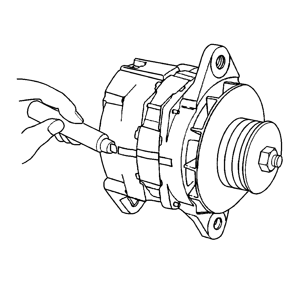
- Hold the generator in a vise.
- Clamp the generator lengthwise onto one mounting lug.
- Scribe a mark onto the generator frame end parts in order to ensure
correct assembly.
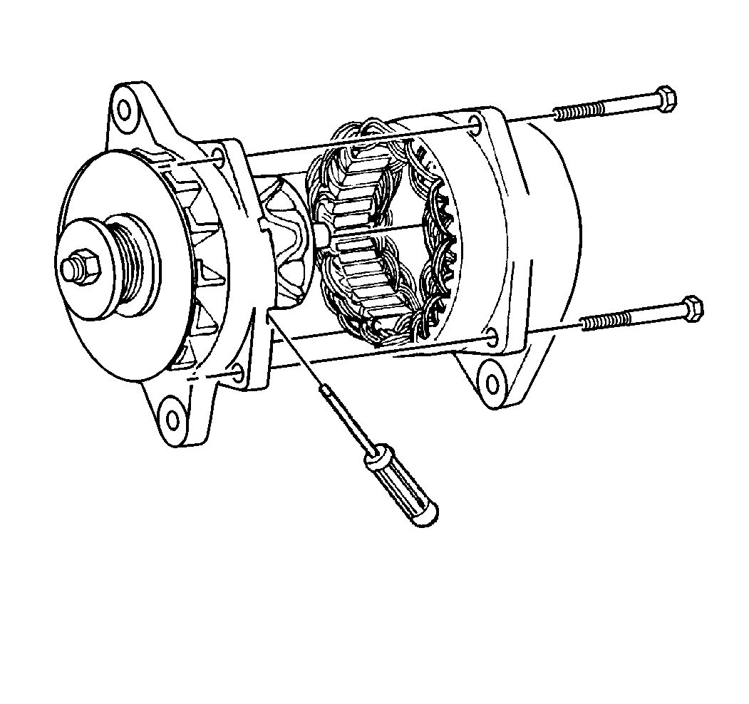
- Remove the four through-bolts.
- Use a screwdriver at the stator slots, if necessary, in order
to remove the slip ring end frame from the following components:
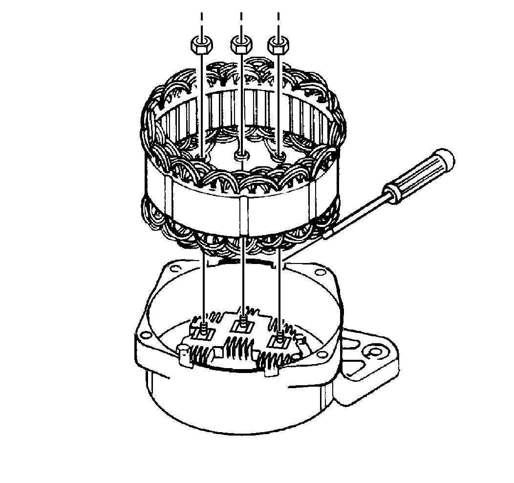
- Remove the three rectifier bridge nuts in order
to disconnect the stator.
- Carefully use a screwdriver, if necessary, in order to remove
the stator from the slip ring end frame.
- Remove the nut from the relay terminal connecting strap.
- Remove the following components from the inside of the frame:
- Remove the threaded relay terminal from the outside of the frame.
- Remove the following parts from the regulator:
| • | The two insulated screws |
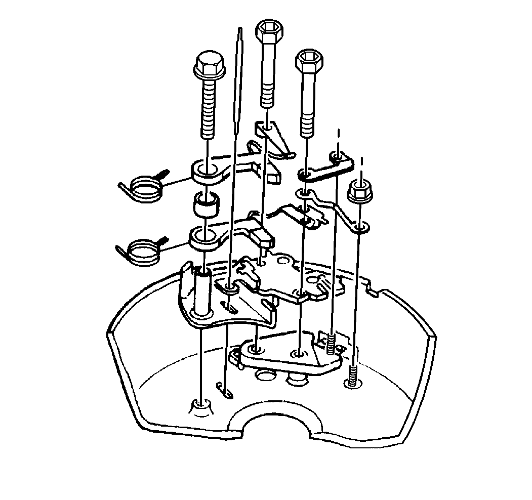
- Remove the following components from the brush
holder.
- Remove the following parts from the end frame:
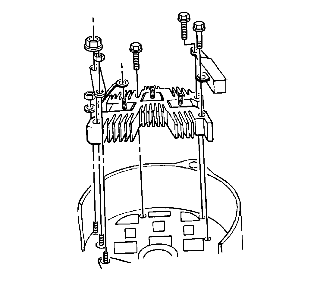
- Remove the screws holding the capacitor to the
following components:
| • | The slip ring end frame |
- Remove the following parts on the BAT terminal from the
rectifier bridge:
| • | The ground screw washer |
- Remove the rectifier bridge from the end frame.
- Remove the following parts from the outside of the frame.
| • | The BAT terminal shield |
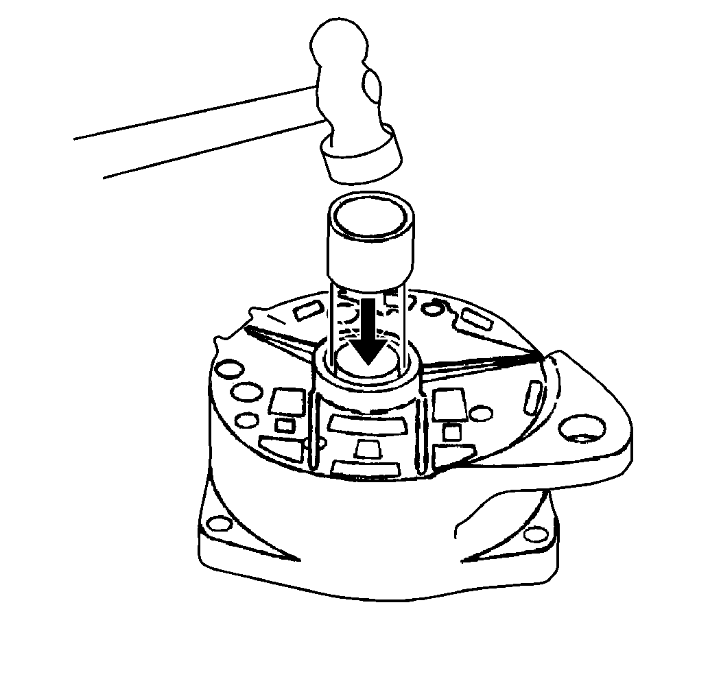
- Use the following procedure in order to remove
the bearing from the slip ring end frame:
| 18.1. | Support the slip ring end frame from the inside. |
| 18.2. | Obtain a tube that has an outside diameter slightly smaller than
the bearing. |
| 18.3. | Use the tube from outside the frame in order to press the bearing
in. |
Drive End Frame Disassembly
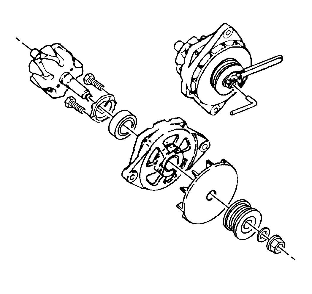
- Use the following procedure in order to remove
the pulley nut:
| 1.1. | Use the 5/16 inch hex-head wrench in order to hold the
end of the shaft. |
| 1.2. | Turn the wrench to the left in order to remove the pulley nut. |
| 1.3. | If a 5/16 inch hex-head wrench is not available, take the
following steps: |
| 1.3.1. | Wrap the rotor in a shop cloth. |
Notice: The rotor may be distorted if the vise is overtightened.
| 1.3.2. | Place the rotor in a vise. |
| 1.3.3. | Tighten the vise in order to hold the rotor while removing the
pulley nut. |
- Remove the washer.
- Remove the pulley.
- Remove the fan.
- Use a puller, if necessary, in order to remove the drive end frame
from the rotor shaft.
- Remove the rotor from the vise.
- Remove the three retainer bolts.
- Remove the retainer.
- Use the following procedure in order to remove the bearing from
the drive end frame:
| 9.1. | Use a metal tube that has an inside diameter slightly larger than
the outside diameter of the bearing in order to support the drive end frame
from the inside. |
| 9.2. | Use a second metal tube against the inner race of the bearing
in order to press the bearing from the drive end frame. |
Cleaning and Inspection Procedure
- Clean all of the metal components except for the following components
in a suitable solvent:
- Use one of the following methods in order to dry the components:
- Inspect the brush holder.
- Inspect the insulating sleeves on the brush holder retaining screws.
- Inspect the brushes.
If the brushes are worn more than halfway, replace the brush assembly.
- Inspect the brush springs for the following conditions:
- Inspect the bearing seals.
If the felt seal in the drive end bearing retainer plate exhibits one
of the following conditions, replace the retainer assembly:
- Inspect the bearings for grease.
Use the following standard in order to replace the bearing:
| • | If the slip ring end bearing grease supply is exhausted, replace
the bearing. |
| • | If the slip ring end bearing grease supply is not exhausted, relubricate
the bearing. Refer to Lubrication in order to use the correct type of lubricant. |
- Replace the rotor and the stator windings if any of the following
conditions exist:
- Inspect the rotor slip rings.
Notice: The rotor must be rotated so that the slip rings will be cleaned evenly.
Cleaning the slip rings by hand without spinning the rotor may result in flat
spots on the slip rings, causing brush noise.
| 10.1. | If the slip rings are dirty, use the following procedure in order to
clean the slip rings: |
| 10.1.1. | Obtain a polishing cloth with a grain of 400 or finer. |
| 10.1.3. | Hold the polishing cloth against the slip rings until the slip
rings are clean. |
| 10.2. | If the slip rings are rough or out of round, use the following
procedure in order to true the rings: |
| 10.2.1. | Use a lathe in order to true the slip rings to 0.05 mm
(0.002 in) maximum indicator reading. |
| 10.2.2. | Remove only enough material in order to make the rings smooth
and round. |
| 10.2.3. | Use a polishing cloth with a grain of 400 or finer in order to
finish the rings. |
| 10.2.4. | Blow away all of the dust. |
- Perform electrical tests on the following components.
| • | Refer to Rotor Field Winding Tests. |
- Inspect the drive end housing for damage.
- Inspect the slip ring end housing for damage.
Rotor Field Winding Tests
Use a self-powered test lamp or an ohmmeter on the low range scale in
order to perform an electrical test the rotor.
Open Circuit Test
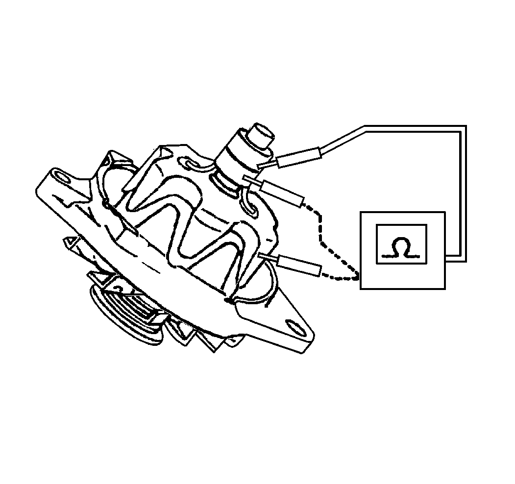
- Connect the ohmmeter
to each slip ring in order to test for opens.
- The winding is open if the ohmmeter reading is high (infinite).
Short Circuit or Resistance Test

- Use one of the following
two methods in order to test the winding for short-circuits or excessive resistance:
Using an Ammeter
| 1.1. | Connect a 12 volt battery and an ammeter in series with
the edges of the two slip rings. |
| 1.2. | Compare the reading on the ammeter to the specified values for
21-SI 200 generators. Refer to
Generator Usage
. |
| 1.3. | Use the following procedure in order to identify a short circuit
or excessive resistance. |
| • | If the ammeter reading is above the specified value, then the
windings are shorted. |
| • | If the ammeter reading is below the specified value, then the
resistance is excessive. |
Using an Ohmmeter
| 1.1. | Connect an ohmmeter to the two slip rings. |
| 1.2. | Compare the reading on the ohmmeter to the specified values for
21-SI 200 generators. Refer to
Generator Usage
. |
| 1.3. | If the resistance reading is below the value specified value,
then the resistance is excessive. |
- Use the following guides in order to diagnose winding malfunctions:
| • | The winding resistance and ammeter readings will vary slightly
according to temperature changes in the winding. |
| • | If the rotor is good but the generator fails to supply the rated
output, then the problem is in one of the following components: |
| • | Use the following procedure in order to test for grounds: |
| 1. | Connect the ohmmeter as shown. |
| 2. | Replace the rotor if the reading is less than infinite. |
- Replace the rotor if the results of the rotor tests are not within
specifications.
Diode Trio Test
Use an ohmmeter with a 1.5 volt cell set to the
lowest range scale in order to test the diode trio. Use the following procedure:
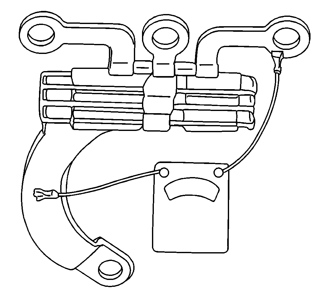
- Place the negative lead
of the ohmmeter on the regulator strap.
- Use the positive lead of the ohmmeter in order to test for continuity
between each of the three rectifier bridge straps.
- Ensure that all three readings indicate continuity.
- Reverse the ohmmeter leads.
- Perform the test again.
- Ensure that all three readings indicate open circuits.
Important: The ohmmeter test of the diode trio is a valid and accurate test. Do
not replace the diode trio unless at least one pair of readings is the same.
- Replace the diode trio if any of the readings are wrong.
Rectifier Bridge Test
Use an ohmmeter with a 1.5 volt cell set to the
lowest range scale in order to test the rectifier bridge. Use the following
procedure:
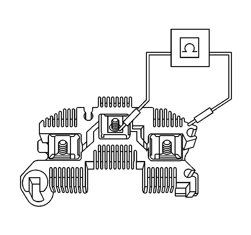
- Connect an ohmmeter to
the following components in order to test the rectifier bridge:
| • | One of the three flat metal connectors |
| • | Do not bend the flat metal clips. |
- Observe the ohmmeter reading.
- Reverse the lead connections to the grounded heat sink and the
same flat metal connector.
- A good rectifier bridge will show one high reading and one low
reading. If both readings are the same, then replace the rectifier bridge.
- Repeat the above test procedure between the grounded heat sink
and the other two connectors.
- Repeat the above test procedure between the insulated heat sink
and each of the three connectors.
Important: The ohmmeter test of the rectifier bridge is a valid and accurate test.
Do not replace the rectifier bridge unless at least one pair of readings
is the same.
- Complete a total of six tests using two readings for each test.
Stator Tests
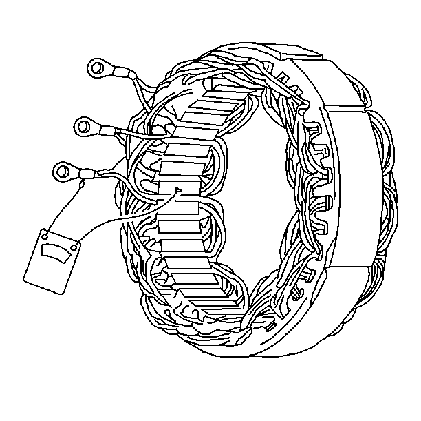
- Use a ohmmeter in order
to test the stator windings.
- If the meter reading is low when connected from any stator lead
to the frame, then the windings are grounded. Refer to
Generator Usage
.
Important: Locating an open or a short circuit in the delta stator windings is
difficult without using laboratory test equipment. Locating an open
or a short circuit in the delta stator windings is difficult because
of the low resistance of the windings. The following conditions indicate
shorted or open delta windings:
| • | All other electrical test are normal. |
| • | The generator does not produce within 15 amps of the rated
output. |
- If the windings are grounded, replace the stator.
Testing the Regulator
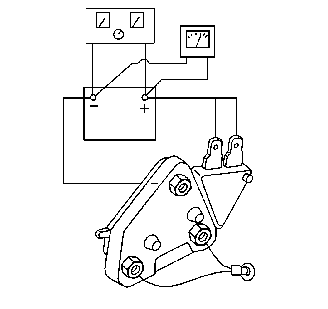
- Connect the following
items to the 12 volt battery
- Connect the following components:
- Observe the polarity of the battery.
- Verify that the test lamp is ON.
- Turn ON the fast charger.
- Slowly increase the charge rate.
- Observe the voltmeter.
- Verify that the lamp turns OFF at the voltage regulator setting.
- Verify that the voltage regulator setting is a minimum of 13.5 volts
and a maximum of 15.5 volts.
The test lamp connects into the circuit exactly as the
rotor is when the regulator is inside the generator. The regulator shuts off
the current to the test lamp when the voltage reaches the regulator setting.
If you cannot test the regulator, and the regulator is questionable
after testing the other components, replace the regulator with a new or a
known good regulator.
Generator Assembly
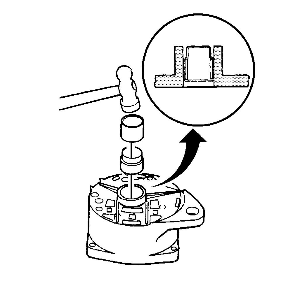
- Use the following procedure in order to install the bearing into the
slip ring end frame:
| 1.1. | Support the inside of the frame. |
| 1.2. | Use a thin wall tube in the space between the grease cup and the
housing in order to push the bearing in flush with the housing. |
- Use the following procedure in order to install the bearing into
the drive end frame:
| 2.1. | Support the drive end frame on a flat surface. |
| 2.2. | Use a tube against the outer race of the bearing in order to press
the bearing in. |
- Install the retainer.
Notice: Use the correct fastener in the correct location. Replacement fasteners
must be the correct part number for that application. Fasteners requiring
replacement or fasteners requiring the use of thread locking compound or sealant
are identified in the service procedure. Do not use paints, lubricants, or
corrosion inhibitors on fasteners or fastener joint surfaces unless specified.
These coatings affect fastener torque and joint clamping force and may damage
the fastener. Use the correct tightening sequence and specifications when
installing fasteners in order to avoid damage to parts and systems.
- Install the three
retainer screws.
Tighten
Tighten the three retainer screws to 3 N·m (26 lb in).
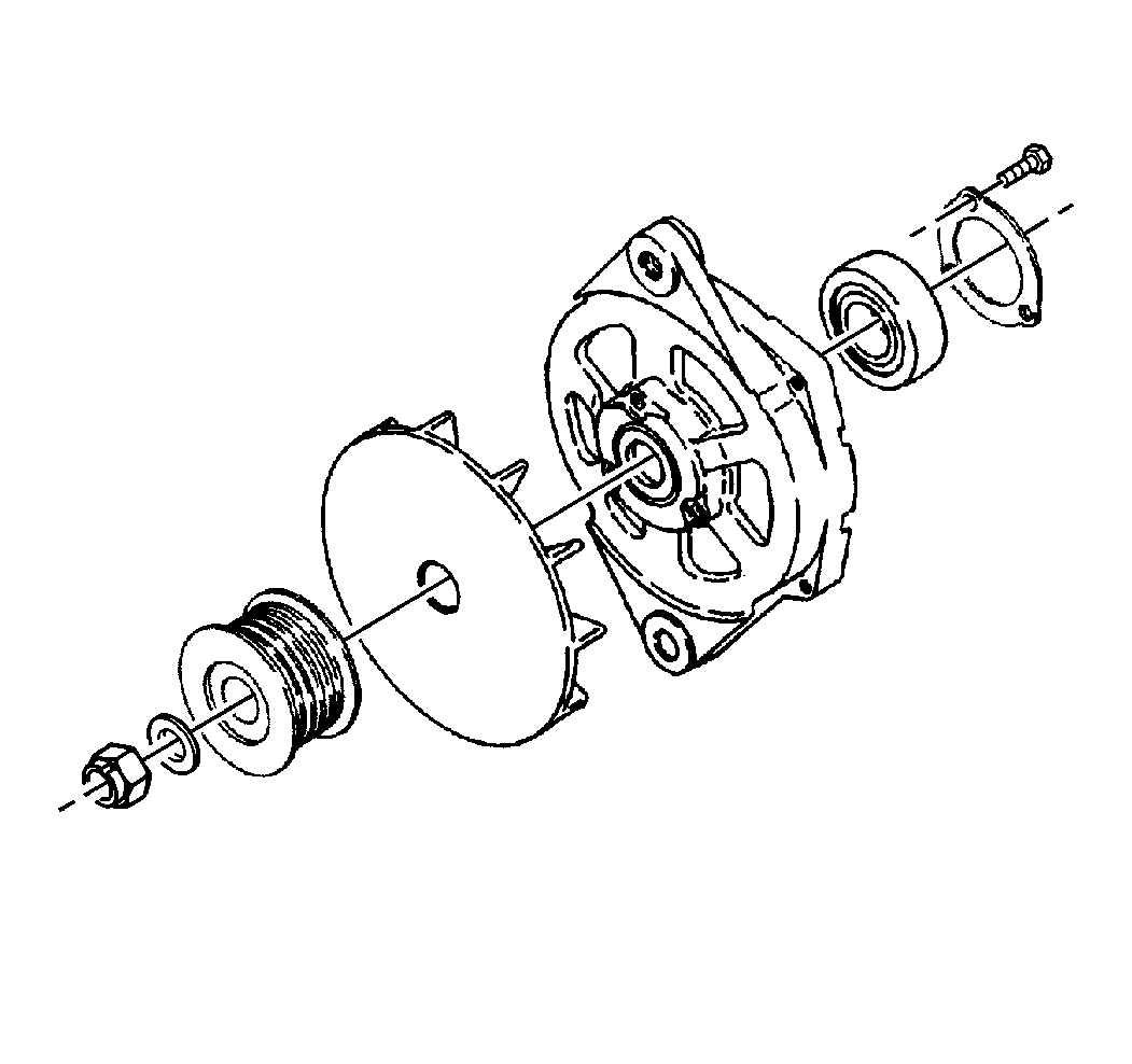
- Install the drive end
frame onto the rotor shaft.
- Install the fan.
- Install the pulley.
- Install the washer.
- Install the pulley nut.
Notice: Too much pressure applied against the rotor will distort it.
- Place the rotor in a vise.
Tighten the vise only enough to tighten the pulley nut.
Tighten
Tighten the pulley nut to 100 N·m (74 lb ft).
- Remove the assembly from the vise.
- Install the following components onto the slip ring end frame:
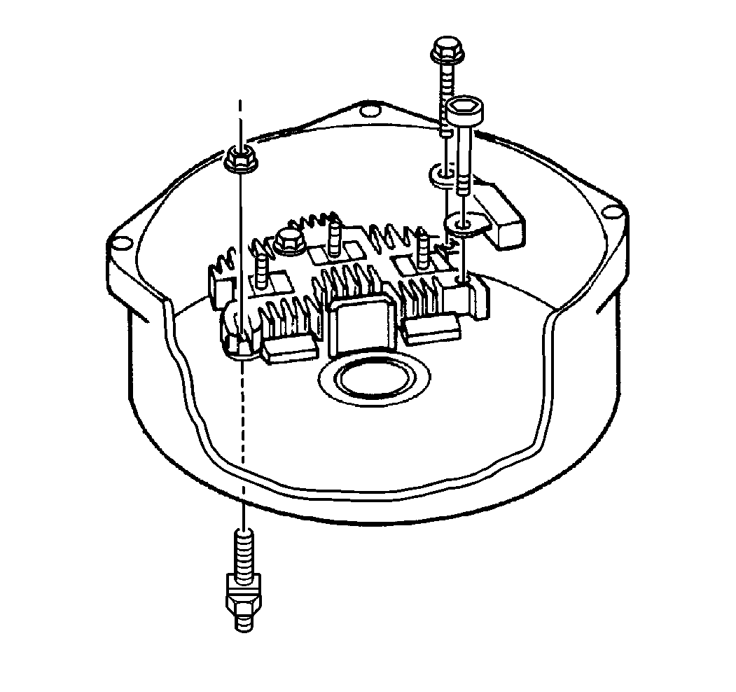
- Use the following components
in order to secure the rectifier bridge and the capacitor to the slip ring
end frame:
Tighten
| • | Tighten the ground screws to 3 N·m (25 lb in).
|
| • | Tighten the insulated screw to 2.5 N·m (22 lb in).
|
- Install the BAT terminal from the outside of the slip ring
end frame.
- Install the nut onto the BAT terminal stud.
Tighten
Tighten the nut to 5.5 N·m (50 lb in).
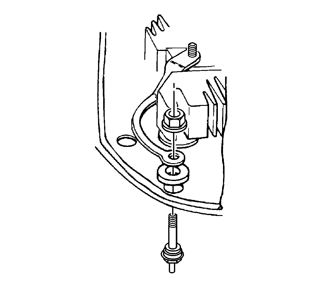
- Install the relay terminal
from the outside of the slip ring end frame.
- Use the copper nut in order to secure the insulated washer and
the attaching strap from the rectifier bridge to the relay terminal.
Tighten
Tighten the copper nut to 2.5 N·m (22 lb in).
- Install the brushes into the brush holder assembly.
- Use a retainer in order to retain the brushes.
- Ensure that the long end of the retainer extends through the end
frame in order that you are able to remove the retainer after you install
the rotor and the drive end frame.
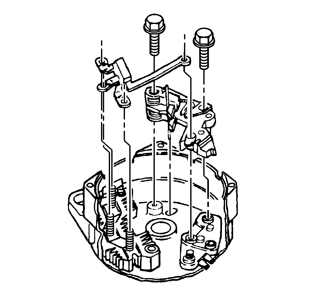
- Install the following
components to the end frame:
| • | The brush holder assembly |
- Use the following components in order to secure the regulator,
the brush holder assembly and the diode trio to the end frame:
- Install the nut onto the stud on the regulator:
Tighten
Tighten the nut to 2.5 N·m (22 lb in).
- Install the stator to the following components:
| • | The slip ring end frame |
| • | The three rectifier bridge terminals |
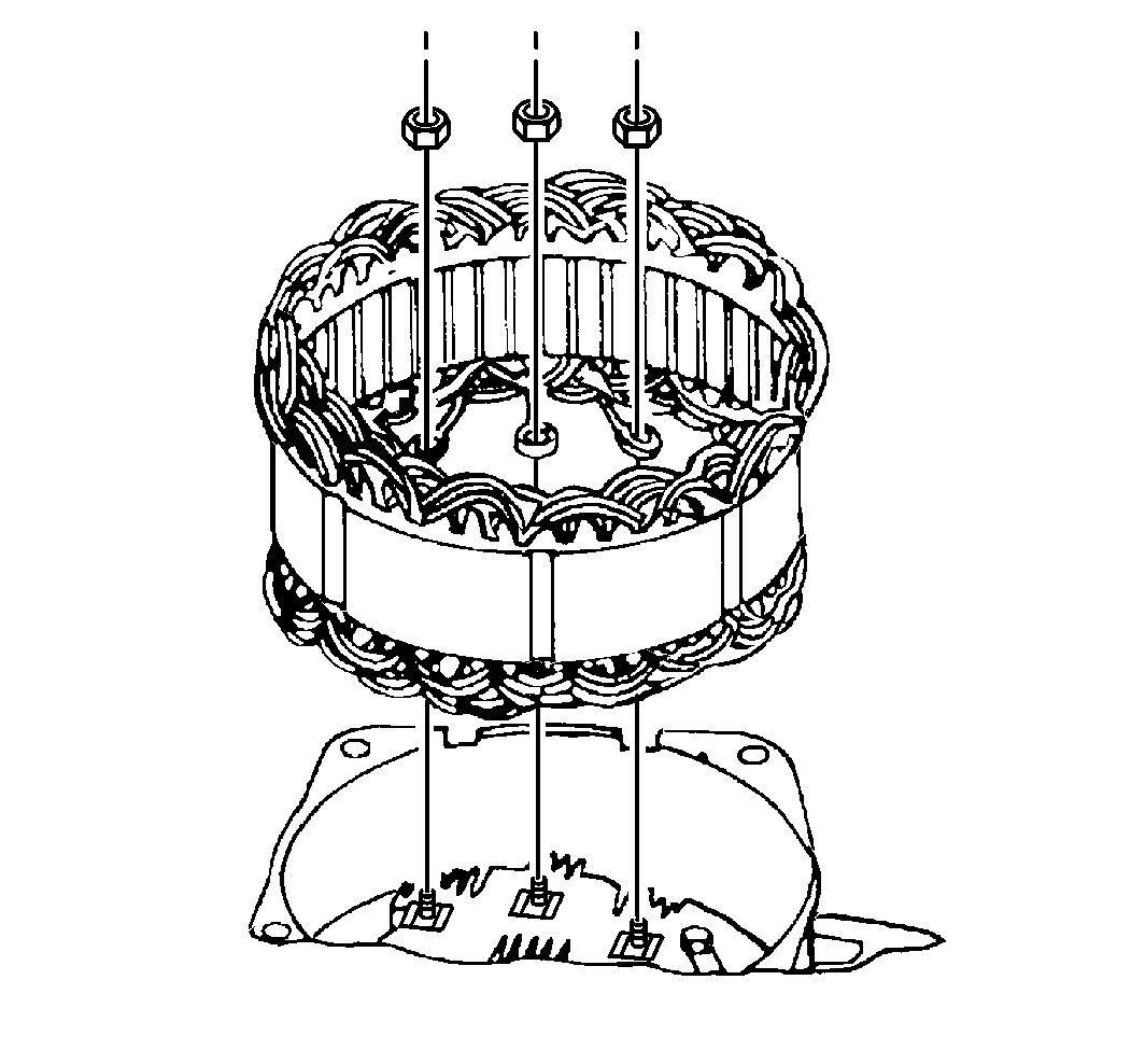
- Use the three terminal nuts in order to secure the following components
to the rectifier bridge:
Tighten
Tighten the nuts to 2.5 N·m (22 lb in).
- Use the scribe mark in order to line up the following components
to the slip ring end frame:
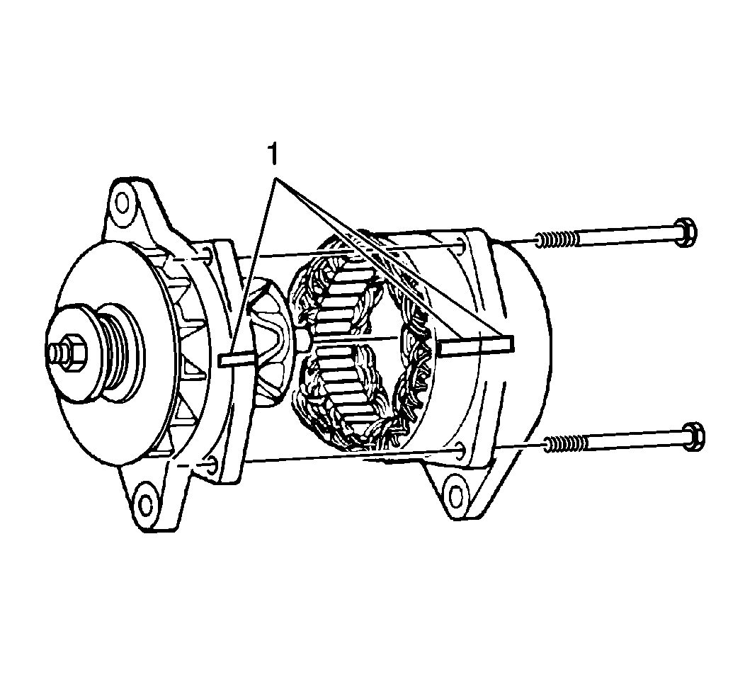
- Use the four through-bolts
in order to secure the following components to the slip ring end frame:
| • | The drive end frame (1) |
Tighten
Tighten the through-bolts to 5.5 N·m (50 lb in).
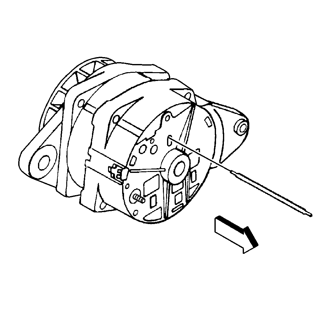
- Remove the brush retainer
from the end frame.
- Test the generator output.


