Purpose
The evaporative emission (EVAP) control system limits the fuel vapors from escaping into the atmosphere. The EVAP transfers the fuel vapor from the sealed fuel tank to an activated carbon (charcoal) storage device (EVAP canisters). The EVAP canisters stores the vapors until the engine is able to use the extra fuel vapor.
When the engine is able to use the extra fuel vapor, the intake air flow purges the fuel vapor from the carbon element, and then the normal combustion process consumes the fuel vapor.
The fuel tank is sealed with a fuel cap that is not normally vented to atmosphere. The fuel tank cap has a safety valve which allows for both pressure and vacuum relief.
Operation
Fuel vapors from the fuel tank purge and flow into the EVAP canister tube labeled Tank and the carbon absorbs the vapors. The canister purges when the engine is able to use extra fuel vapor. A vacuum source is applied to the EVAP canister tube labeled Purge to draw fresh air through the bottom of the canister. The air mixes with the fuel vapor and the mixture is drawn in the intake manifold to be consumed in the normal combustion process.
While the canister is purging, fresh air is drawn in through the air inlet and through the bottom of one canister. Air flows to the top of the canister and goes through a crossover pipe to the other canister and forces the vapors out the Purge tube.
The EVAP system in some applications uses an electrically controlled solenoid to cycle the vacuum to the purge canister. The control module cycles the solenoid when the engine coolant temperature is greater than 45°C or the Short Term Fuel Trim counter is less than 122.
A vacuum switch in the purge line detects when the system is purging. The normally closed switch will open when less than 1 inch Hg is present in the purge line.
EVAP Canister Location

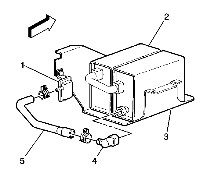
The EVAP canisters (2) are located on the right side frame rail near the fuel tank.
EVAP Air Inlet Location

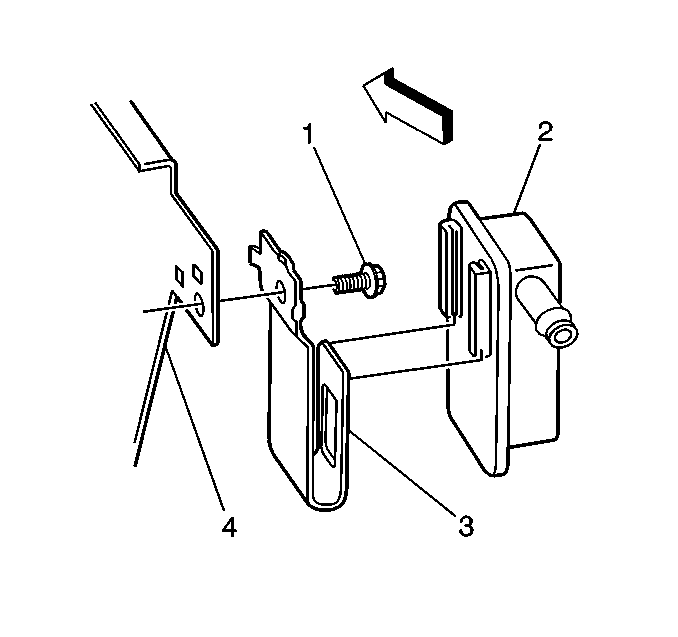
The EVAP air inlet (2) is located on the EVAP canister bracket assembly (4).
