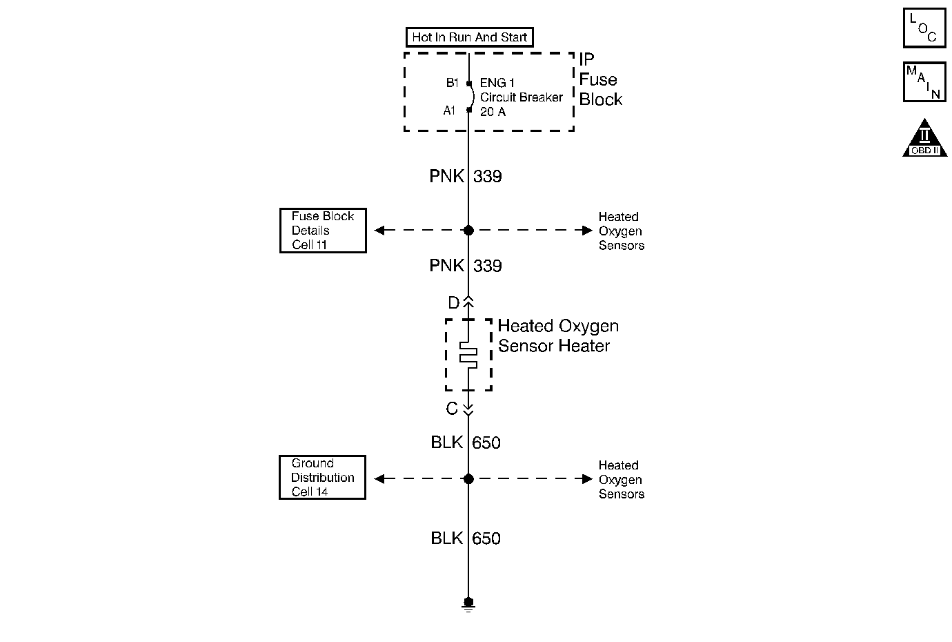
Circuit Description

The PCM supplies a bias voltage (approximately 450 mV) on the Heated Oxygen Sensor (HO2S) signal high and low circuits. When the ignition is turned to the ON position, battery voltage is supplied to the HO2S heater. As the heater reaches the operating temperature, the HO2S voltage responds by changing from a bias voltage range to the normal operation. Typically, as the HO2S reaches the operating temperature, the HO2S voltage goes from a bias voltage to a voltage below 300 mV. Depending on the exhaust gas content, it is possible for the HO2S voltage to go above 450 mV.
The time the process takes the HO2S to reach operating temperature is based on the amount of air that flows into the engine.
Test Description
The numbers below refer to the step numbers on the diagnostic table.
-
Allow the engine to cool before performing this test. If the sensors are at the operating temperature the HO2S voltages will stay high or low. If a HO2S voltage stays between 300-700 mV indicates a HO2S heater is inoperative. For any test that requires probing the PCM or a component harness connector, use the Connector Test Adapter Kit J 35616 . Using this kit will prevent damage to the harness connector terminals.
-
If none of the HO2S voltages indicate a sufficient change in voltage, this is a good indication that the fuse is open. Check all the related circuits going to all the heated oxygen sensors for a short to ground. If all the wiring checks to be OK, it may be necessary to disconnect each HO2S one at a time to locate a shorted sensor.
-
This step checks whether ignition positive voltage is available at the sensor.
-
This step checks whether a ground is available at the sensor.
-
This step checks whether the HO2S heater element is internally open.
Step | Action | Value(s) | Yes | No |
|---|---|---|---|---|
1 | Did you perform the Powertrain On-Board Diagnostic (OBD) System Check? | -- | ||
|
Important: Allow the engine to cool for about one half hour before proceeding with this table.
Did all the HO2S voltages go from a bias voltage to above or below the specified range? | 300-700 mV | System OK | ||
Did any HO2S voltages go from a bias voltage to above or below the specified range? | -- | |||
Does the test lamp illuminate? | -- | |||
Connect the test lamp J 35616-200 between the HO2S ignition feed and the HO2S heater ground. Does the test lamp illuminate? | -- | |||
Measure the resistance between the HO2S ignition feed and the HO2S heater ground at the HO2S pigtail using a DMM J 39200 . Is the HO2S resistance within the specified range? | 3.5-14.0 ohms | |||
7 | Repair the open in the HO2S ignition feed circuit to the HO2S. Refer to Wiring Repairs in Wiring Systems. Is the action complete? | -- | -- | |
8 | Repair the open in the HO2S heater ground circuit. Refer to Wiring Repairs in Wiring Systems. Is the action complete? | -- | -- | |
9 |
Did you find and repair a poor connection? | -- | ||
10 | Replace the HO2S. Refer to Heated Oxygen Sensor Replacement - Bank 1 or Heated Oxygen Sensor Replacement - Bank 2 . Is the action complete? | -- | -- | |
11 |
Is the action complete? | -- | -- | |
12 |
Did all the HO2S voltages go from a bias voltage to above or below the specified range? | -- | System OK |
