Removal Procedure
Tools Required
- Block the wheels.
- Support the propeller shaft assembly.
- Remove the propeller shaft. Refer to the following procedures:
- Remove the universal joint from the yoke. Refer to
Universal Joint Replacement
.
- Remove the bracket mounting bolts and nuts.
- Remove the bracket and retainer.

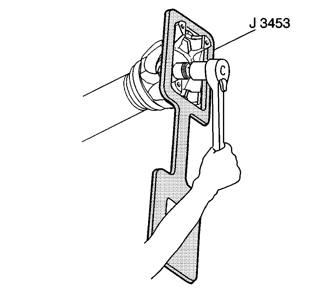
- Remove the yoke nut using
the J 3453
.

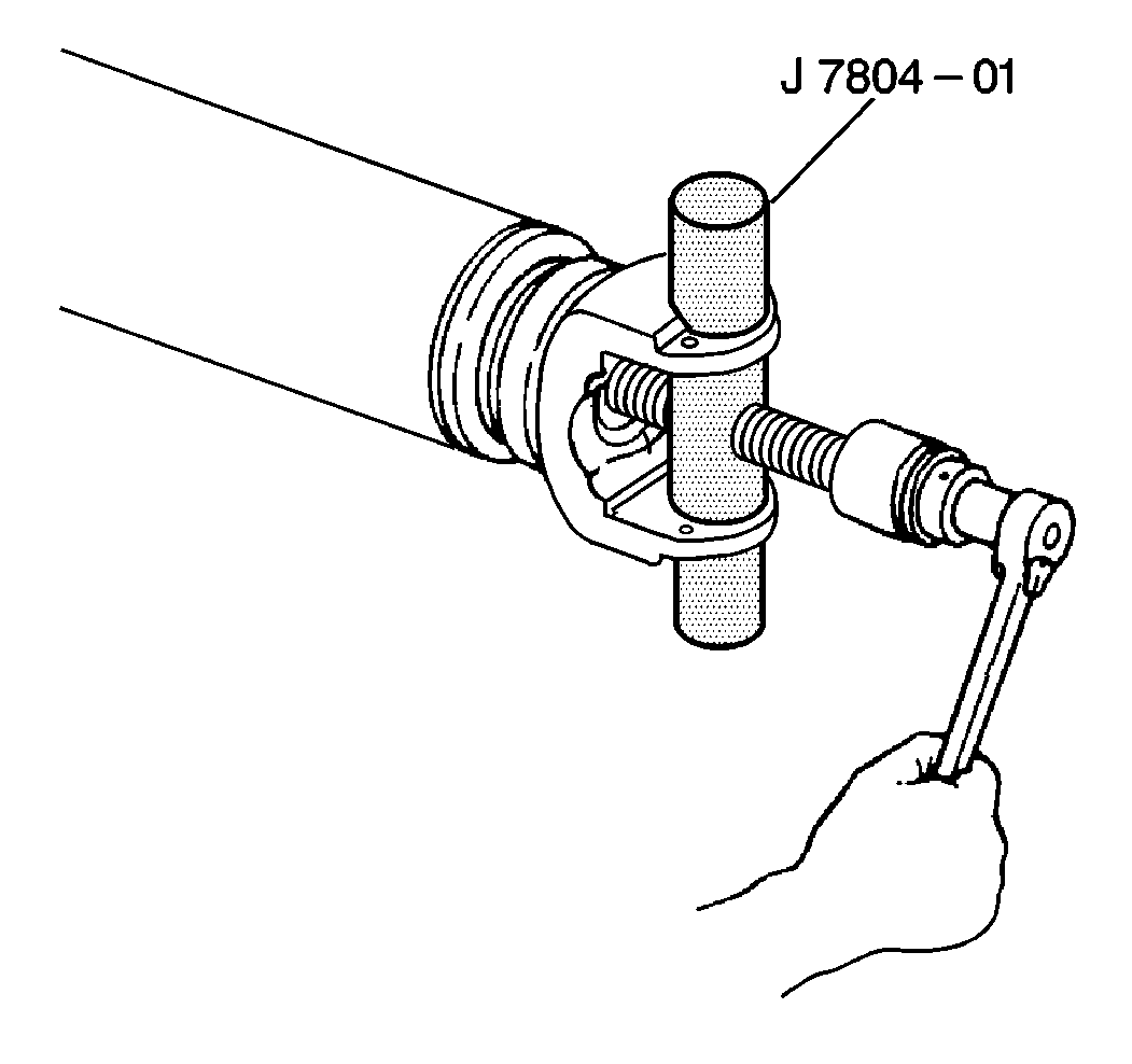
- Remove the yoke from the
propeller shaft using the J 7804-A
.
- Remove the slinger.
- Remove the grease retainer, if equipped.

- Remove the center bearing
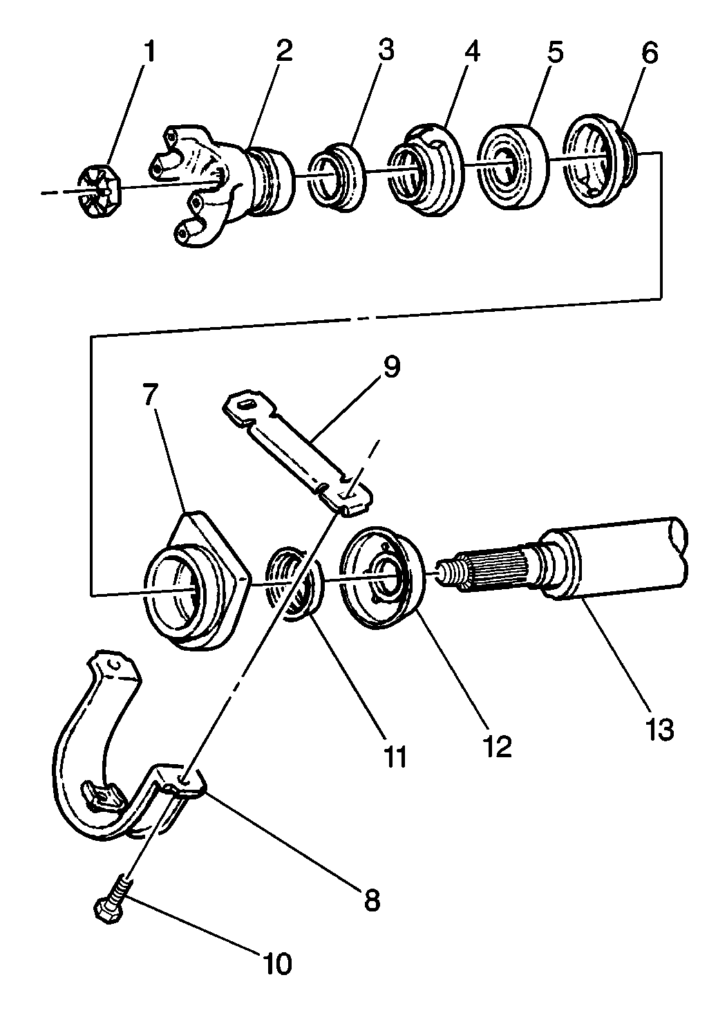
(5).
- Remove the grease retainer (4,6) if equipped.
- Remove the rubber cushion (7).
- Remove the slinger (11) and dust shield (12), if used.
- Clean the slingers.
- Clean the grease retainers.
- Clean the rubber cushion.
- Inspect the center bearing for wear or damage.
- Inspect the rubber cushion for cracks or distortion.
- Inspect the slingers and grease retainers for wear or damage.
Installation Procedure
- Install the lubricant into the grease retainers, if equipped.
Refer to
Fluid and Lubricant Recommendations
.

- Install the grease retainers
(4,6) if equipped, to the center bearing (5).
- Install the center bearing (5) into the rubber cushion (7).
- Install the dust shield (12), if used.
- Install the slinger (11).
- Install the center bearing (5) on the propeller shaft (13).
- Install the slinger (11) on the propeller shaft (13).
- Install the yoke (2).
Notice: Use the correct fastener in the correct location. Replacement fasteners
must be the correct part number for that application. Fasteners requiring
replacement or fasteners requiring the use of thread locking compound or sealant
are identified in the service procedure. Do not use paints, lubricants, or
corrosion inhibitors on fasteners or fastener joint surfaces unless specified.
These coatings affect fastener torque and joint clamping force and may damage
the fastener. Use the correct tightening sequence and specifications when
installing fasteners in order to avoid damage to parts and systems.
- Install the yoke
nut using the J 3453
.
Tighten
| • | Tighten the series 1480 nut to 779 N·m (575 lb ft) |
| • | Tighten the series 1550 bolt to 216 N·m (160 lb ft) |
| • | Tighten the series 1610, 1710, 1710HD or 1760 nut to 983 N·m
(725 lb ft) |
- Install the bracket (8) and the retainer (9) to the rubber cushion
(7).
- Install the propeller shaft. Refer to the following procedures:
- Install the mounting bolts (10) and nuts.
Tighten
Tighten the propeller shaft hanger nuts to 70 N·m (52 lb ft)
- Install the universal joint. Refer to
Universal Joint Replacement
.
- Remove the wheel blocks.


