Parking Brake Shoe Replacement Bendix 229mm - 9in
Removal Procedure

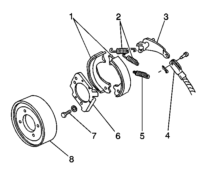
- Remove the drum (8). Refer
to
Park Brake Support Replacement
.
- Remove the return springs (2).
- Remove the anchor springs (5).
- Remove the linings (1).
- Spread the brake shoes apart.
- Inspect the linings (1) for contamination.
- Inspect the linings (1) for excessive wear. The minimum thickness
(with bonded linings) is 1.52 mm (0.60 in).
- Replace the linings (1) as a set, if necessary.
- Inspect the springs for distortion.
- Replace the springs, if necessary.
- Inspect the cam lever (3) for grooves at the brake shoe contact
points.
- Replace the cam lever (3), if necessary.
Installation Procedure

- Install the linings (1).
- Place the cam lever (3) in position with the two fingers between
the shoe webs.
- Install the anchor spring (5).
- Use GM P/N 1051344 or the equivalent in order to
lubricate the points where the brake shoes contact the support plate (6).
- Install the return springs (2).
- Install the drum.
- Adjust the parking brake. Refer to
Park Brake Support Replacement
.
Parking Brake Shoe Replacement Bendix 305mm - 12in
Removal Procedure

- Remove the drum. Refer to
Brake Drum Replacement
.
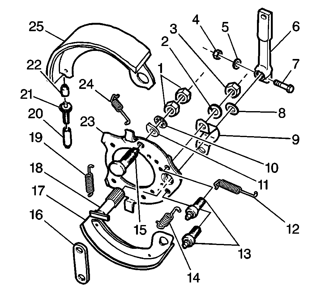
- Remove the return springs (14, 24).
- Remove the link (16).
- Remove the linings (17, 25).
- Pull the linings (17, 25) outward and twist the linings in order
to clear the anchor pins (13).
- Overlap the linings (17, 25) in order to remove the adjusting
screw (21) assembly.
- Remove the adjusting screw spring (19).
- Remove the socket (22).
- Remove the adjusting screw (21) out of the pivot nut (20).
- Inspect the linings (17, 25) for contamination.
- Inspect the linings (17, 25) for excessive wear. The minimum lining
thickness is 1.52 mm (0.60 in).
- Replace the linings, if necessary.
Always replace the linings as a set.
- Inspect the return springs and the adjusting screw spring (19).
The return springs and the adjusting screw spring should not have a loss of
tension or openings in the coils.
- Replace the return springs and the adjusting screw spring (19),
if necessary.
- Inspect the shoe webs where there is contact with the camshaft
(18).
- Replace the linings if the shoe webs are severely worn.
- Inspect the adjusting screw (21) and the pivot nut (20) for nicked
or sheared threads.
- Replace the adjusting screw (21) and the pivot nut (20), if necessary.
- Inspect the support plate (23) for damage, distortion and corrosion.
- Remove corrosion from the contact surfaces with a fine emery cloth.
- Replace the support plate (23) if there is damage or distortion.
Installation Procedure

- Apply a thin coat of GM P/N 1051344 or the equivalent to the surface
of the support plate (23) and the support plate guides.
- Coat the threads and the socket end of the adjusting screw (21)
sparingly with GM P/N 1051344 or the equivalent.
- Install the adjusting screw (21) assembly in the following order:
| 3.1. | Thread the adjusting screw (21) all of the way into the pivot
nut (20). |
| 3.2. | Place the adjusting screw socket (22) over the end of the adjusting
screw (21). |
- Install the adjusting screw (21) assembly between the adjusting
ends of the brake shoes. The star wheel must be closer to the top lining (25).
- Install the spring (14).
- Move the anchor ends of the linings (17, 25) together in order
to overlap the shoe webs.
- Install one lining (17, 25) on the guides of the support plate
(23).
- Lubricate the anchor pins (13) where the anchor pins contact the
shoe webs with GM P/N 1051344 or the equivalent.
- Twist the lining slightly in order to clear the end of the anchor
pin (13) and position the lining over the pin.
- Install the second lining (17, 25).
- Install the link (16).
- Install the return springs.
- Install the drum. Refer to
Brake Drum Replacement
.
- Adjust the parking brake. Refer to
Parking Brake Shoe Adjustment
.
Parking Brake Shoe Replacement Rockwell 305mm - 12in
Removal Procedure

- Block the
wheels.
- Release the parking brake.
- Remove the drum. Refer to
Brake Drum Replacement
.
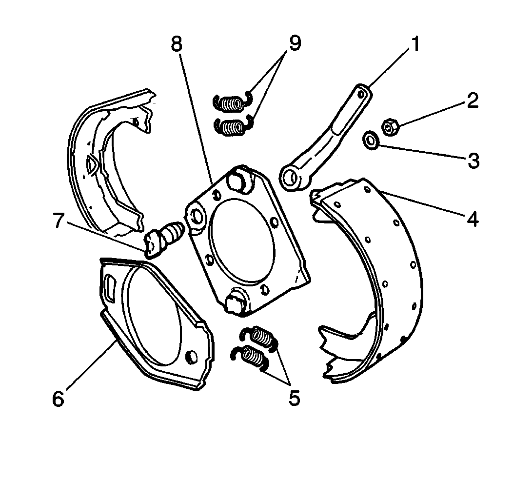
- Remove the nut (2).
- Remove the washer (3).
- Remove the camshaft (7).
- Remove the lever (1).
- Remove the return springs (5).
- Discard the old return springs.
- Replace the old return springs with new return springs.
Important: Closely examine the linings for contamination and excessive wear.
- Remove the linings (4).
- Mark each brake shoe in order to ensure that the assembly will
be in the same position.
Important: Closely examine all of the mounting bolt holes in the drum for stress
cracks.
- Inspect the drum for the following damage:
- Replace the drum if necessary.
Installation Procedure

- Install the linings (4).
- Align the marks on each shoe in order to ensure that the linings
are assembled in the original position.
- Install new return springs (5).
- Install the camshaft (7).
- Install the lever (1).
- Install the nut (2).
- Install the washer (3).
- Install the drum. Refer to
Brake Drum Replacement
.
- Adjust the parking brake. Refer to
Parking Brake Shoe Adjustment
.


