Clutch Assembly Adjustment 14 Inch Valeo Internal Adj.
14 Inch Valeo Clutch System

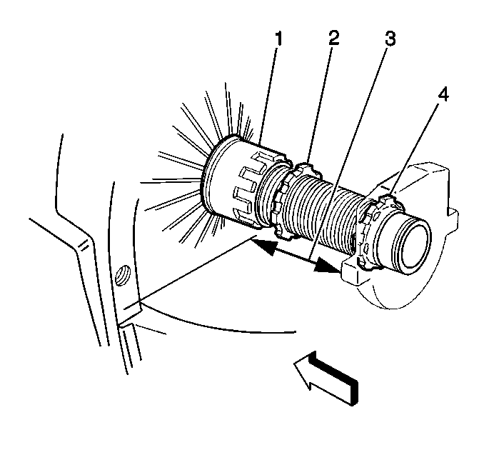
- Measure the distance from the flywheel
housing to the release bearing pads with 25 N·m (6 lb)
of force pulling the bearing toward the transmission.
| 1.1. | If 99.9 mm (0.750 in) on transmissions without a
clutch brake, no adjustment is necessary. |
| 1.2. | If 92.7 mm (0.50 in) on transmissions with a clutch
brake, no adjustment is necessary. |
| 1.3. | If the release bearing position is incorrect, loosen the lock
rings and turn the adjusting nut in order to achieve the proper distance. |
- Tighten the lock ring securely against the release lever spider.
Clutch Assembly Adjustment Dana/Spicer Internal Adj.
Driven Plate (Dana/Spicer®)

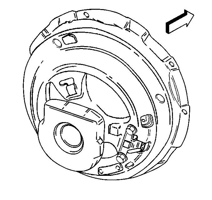
- Remove the hand hole cover from the clutch
housing.
- Depress the clutch in order to move the adjusting ring for the
adjustment of the bearing position.
- Insert a boxed end wrench through the inspection hole.
- Depress the square headed bolt in order to adjust the clutch.
| • | The KWIK-Adjust will re-engage at a quarter of a turn. |
| • | The flat on the bolt head will align with the flat edge of the
bracket. |
Important: For synchronized transmissions, turn the adjusting bolt in order to
obtain approximately 17.8 mm (0.7 in) clearance between the
clutch cover and the release bearing.
For non-synchronized transmissions, turn the adjusting bolt in
order to obtain approximately 18.6 mm (0.73 in) clearance between
the clutch cover and the release bearing.
- Turn the adjusting bolt in order to adjust the release bearing.
| • | A counterclockwise movement of the adjusting bolt moves the release
bearing toward the engine. |
| • | A clockwise movement of the adjusting bolt moves the release bearing
toward the transmission. |
- After the correct bearing position is achieved, ensure the KWIK-Adjust
is engaged in the locked position.
- Release the clutch pedal in order to engage the clutch.
- Start the engine and check the clutch system for proper operation.
- Install the hand hole cover to the clutch housing.
Clutch Assembly Adjustment 13 Inch Valeo Cable Adjustment
13 Inch Valeo Push Type Clutch Cable Adjustment

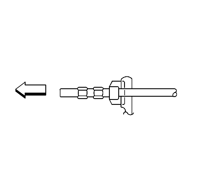
- Apply the parking brake.
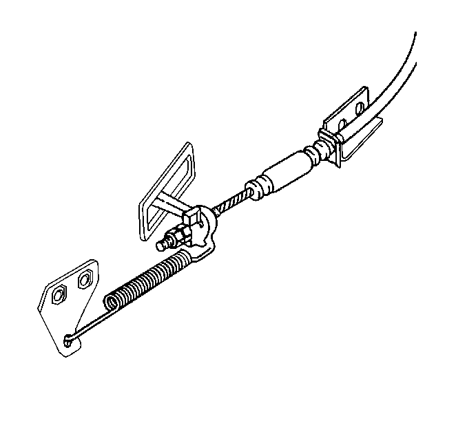
- Remove the clutch return spring from the side of the transmission
- Loosen the jam and adjusting nut
- Using a suitable spring scale, apply 2.2 kg (5 lb)
to 3.1 kg (7 lb) and pull rearward on the clutch lever.
- Using a suitable spring scale, apply 2.7 kg (6 lb)
and pull in the opposite direction.
- Ensure that the clutch pedal is agaisnt the rubber stop.

- Adjust the adjusting nut
down the threads until the adjusting nut is in contact with the spacer block.
- Use a 3/8 inch drive socket extension as a gage.
- Position the end of the 3/8 inch drive (square end) socket extension
on the side of the adjusting nut.
- Adjust the jam nut until the threads are against the side of the
3/8 (square end) drive socket extension.
- Ensure the jam nut does not move.
- Remove the 3/8 drive socket extension.
- Hold the jam nut in place.
- Position the adjusting nut up the threads until it comes in contact
with the jam nut.
- Use a suitable feeler gage to check the clearance between the
clutch fingers and the release bearing.
- Ensure the clearance between the clutch fingers and the release
bearing is 1/8 inch.
Notice: Use the correct fastener in the correct location. Replacement fasteners
must be the correct part number for that application. Fasteners requiring
replacement or fasteners requiring the use of thread locking compound or sealant
are identified in the service procedure. Do not use paints, lubricants, or
corrosion inhibitors on fasteners or fastener joint surfaces unless specified.
These coatings affect fastener torque and joint clamping force and may damage
the fastener. Use the correct tightening sequence and specifications when
installing fasteners in order to avoid damage to parts and systems.
- If the clearance
between the clutch fingers and the release bearing is not 1/8 inch, reposition
the adjusting nut until the proper clearance between the clutch fingers
and the release bearing is achieved.
Tighten
Tighten the jam nut to 40 N·m (30 lb ft).
- Install the return spring.
Important: Use a scale to measure the clutch pedal free play. Record and retain
this information. After normal operation, occasionally check (measure) the
clutch pedal free play. When the distance of clutch pedal free play becomes
half of what was earlier recorded, an adjustment to the clutch cable is
required.
- Check the clutch system for normal operation.
Clutch Assembly Adjustment Clutch Adjustment
14 Inch Valeo Clutch System

- Measure the distance from
the flywheel
housing to the release bearing pads with 25 N·m (6 lb)
of force pulling the bearing toward the transmission.
| 1.1. | If 99.9 mm (0.750 in) on transmissions without a
clutch brake, no adjustment is necessary. |
| 1.2. | If 92.7 mm (0.50 in) on transmissions with a clutch
brake, no adjustment is necessary. |
| 1.3. | If the release bearing position is incorrect, loosen the lock
rings and turn the adjusting nut in order to achieve the proper distance. |
- Tighten the lock ring securely against the release lever spider.
Clutch Assembly Adjustment Internal Clutch Adjustment
14 Inch Valeo Clutch System

- Measure the distance from
the flywheel housing to the release bearing pads with 25 N·m
(6 lb) of force pulling the bearing toward the transmission.
| 1.1. | If 99.9 mm (0.750 in) on transmissions without a
clutch brake, no adjustment is necessary. |
| 1.2. | If 92.7 mm (0.50 in) on transmissions with a clutch
brake, no adjustment is necessary. |
| 1.3. | If the release bearing position is incorrect, loosen the lock
rings and turn the adjusting nut in order to achieve the proper distance. |
- Tighten the lock ring (2) securely against the release lever spider
(1).


