Steering Gear Adjustments TRW Ross
Input Shaft Adjustment Procedure
Important:
| • | Do not rotate the input shaft more than 1½ revolutions
from the center position without the gear installed on the vehicle. This action
could prevent the automatic poppets from operating correctly when the
gear is installed. |
| • | As a result of this action, it would be necessary to disassemble
the steering gear in order to position the poppet seat and sleeve assemblies. |
| • | The components may be automatically adjusted. The components may
also be adjusted manually. Use a service poppet adjusting screw kit in order
to adjust the poppets manually. |
| • | New or reset poppet adjuster seat and sleeve assemblies may be
assembled in the unit. The initial poppet contact will occur at less than
one input shaft rotation in one direction from the steering gear center
position. |
- Rotate the input shaft until the timing mark on the end of the sector
shaft is aligned with the timing mark on the end of the housing.
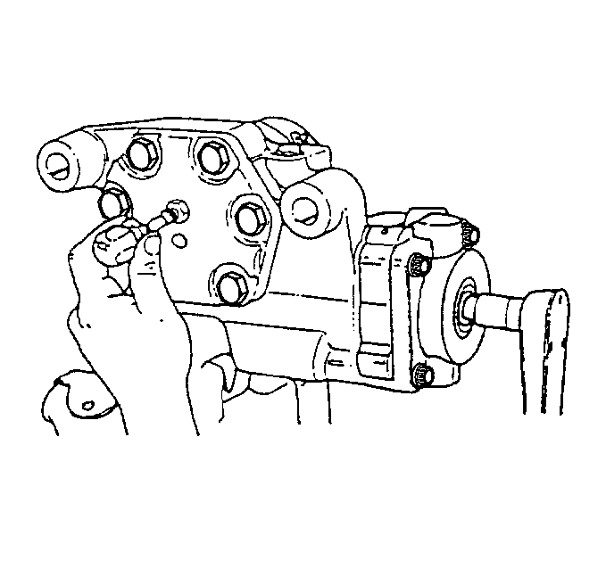
- Use the following steps
in order to seat and correctly mesh the rack piston and the sector shaft teeth
for the final adjustments:
| 2.1. | Ensure that the adjusting screw nut is loose. |
| 2.2. | Turn the sector shaft adjusting screw clockwise in order to provide
5.1-5.6 N·m (45-50 lb in) of torque. |
| 2.3. | Use the force in order to rotate the input shaft through one half
turn to each side of the center. |
- Turn the sector shaft adjusting screw counterclockwise one half
turn in order to rotate the input shaft through one half turn on each side
of the center.
- Turn the sector shaft adjusting screw clockwise in order to increase
the torque above by 0.68 to 0.90 N·m (6 to 8 lb in).
| • | Tighten the jam nut firmly against the side cover while holding
the adjusting screw in position. |
| • | Torque the jam nut to 58 N·m (43 lb ft). |
| • | Inspect the input shaft torque. |
| • | Readjust the input shaft if the torque exceeds 4.5 N·m
(40 lb in). |
Sector Shaft Adjustment Procedure
- Disconnect the relay rod from the pitman arm. Refer to
Relay Rod Replacement
.
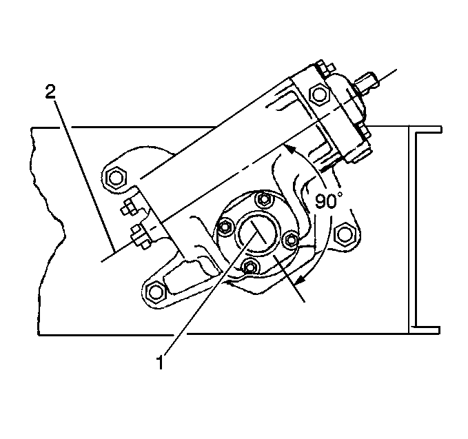
- Rotate the input shaft
until the timing mark (1) on the sector shaft is 90 degrees from the input
shaft center line (2).
The sector shaft MUST be in this position when checking or adjusting
the sector shaft.
- Use the following steps in order to inspect the adjustment of
the pitman arm:
| 3.1. | Grasp the pitman arm. |
| 3.2. | Use light, fingertip force in order to attempt to move the pitman
arm back and forth in its direction of travel. |
(Fingertip force is sufficient to detect a loose sector shaft.)
| 3.3. | If no lash is detected, the adjustment is correct. |
- Remove the gear from the vehicle before adjustment if the following
conditions exist:
| • | The sector shaft adjusting screw is not accessible. |
- Loosen the sector shaft adjusting screw jam nut in order to adjust
the nut.
- Turn the adjuster screw counterclockwise one full turn.
Verify that lash is present at the pitman arm.
- Turn the adjuster screw slowly clockwise until no lash is felt
at the pitman arm.
Notice: Use the correct fastener in the correct location. Replacement fasteners
must be the correct part number for that application. Fasteners requiring
replacement or fasteners requiring the use of thread locking compound or sealant
are identified in the service procedure. Do not use paints, lubricants, or
corrosion inhibitors on fasteners or fastener joint surfaces unless specified.
These coatings affect fastener torque and joint clamping force and may damage
the fastener. Use the correct tightening sequence and specifications when
installing fasteners in order to avoid damage to parts and systems.
- Hold the adjusting
screw in this position and tighten the jam nut.
Tighten
Tighten the sector shaft adjusting screw jam nut 58 N·m
(43 lb ft).
- Use the following steps in order to inspect the pitman arm again
for lash:
| 9.1. | Turn the input shaft (or steering wheel) ¼ turn to each
side of the center. |
| 9.2. | No lash should be present. If lash exists, repeat steps 5-7. |
- Install the gear, if it is removed.
- Connect the relay rod. Refer to
Relay Rod Replacement
.
Steering Gear Adjustments Saginaw - 710 Model
Adjustment Procedure
Tools Required
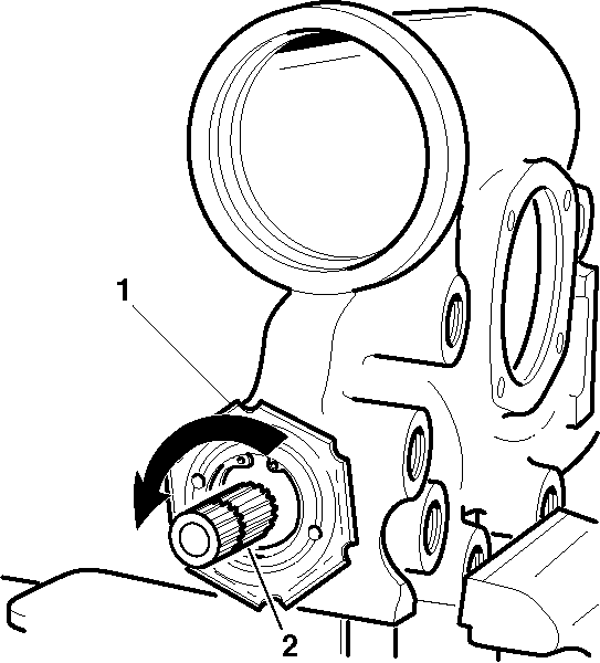
- Drain the oil from the
steering gear by rotating the steering gear completely several times.
- Turn the stub shaft (1) from the right wheel stop to the
left wheel stop while counting the number of turns.
- Rotate the stub shaft (1) back half the number of turns
to the center position.
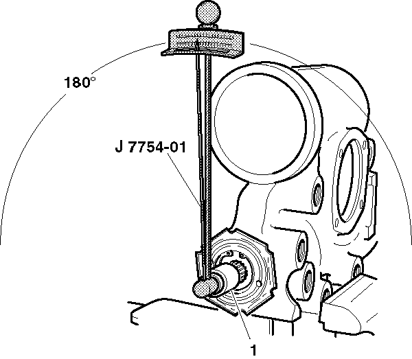
- Place J 7754-01
and a deepwell ¾ inch
12 point socket (1) over the stub shaft in order to check the total
preload torque by rotating J 7754-01
through a 180 degree arc either side of the center.
- Record the highest reading while turning J 7754-01
back over the center position.
- Turn the stub shaft ½ turn (180 degrees)
right or left from the center.
- Install J 7754-01
vertically on the stub shaft.
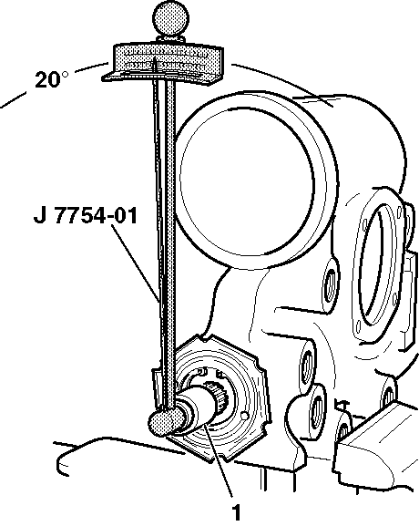
- Turn J 7754-01
20 degrees to the left or the
right of the vertical position.
- Record the reading while turning J 7754-01
back to the vertical position.
- Subtract this reading from the reading in step 5.
- If the reading in step 5 is 0.23 N·m (2 lb in),
then the steering gear is adjusted properly. If the reading in step 5
is less than 0.23 N·m (2 lb in) proceed with
the following adjustments:
| 11.1. | If the reading in step 5 is at least 0.23 N·m
(2 lb in) and not more than 1.13 N·m (10 lb in),
the steering gear is adjusted properly. Proceed to steps 12 through 16. |
| 11.2. | If the reading in step 5 is less than 0.23 N·m
(2 lb in) or more than 1.13 N·m (10 lb in),
proceed to step 12 through 23. |
- Loosen the coupling shield retainer and the lock nut with the
steering gear centered.
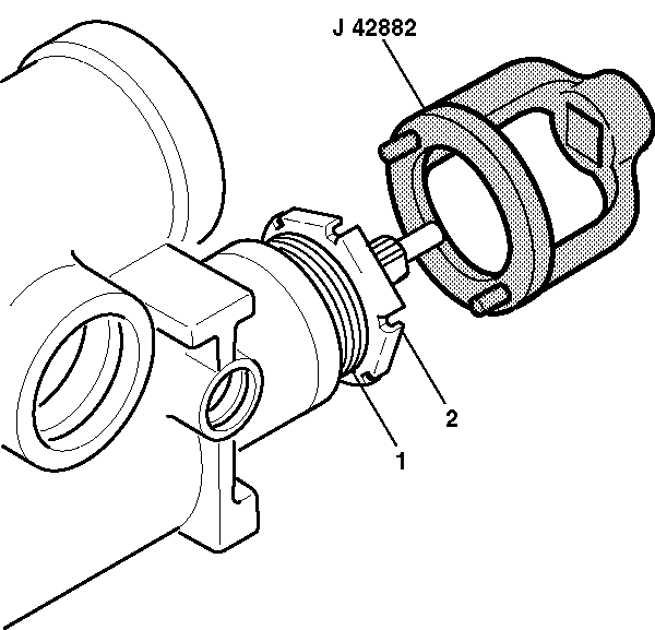
- Turn the adjuster nut
assembly (1) clockwise using J 42882
. Torque the adjuster nut assembly (1) to 28-31 N·m
(21-23 lb ft) and back off 15-25 degrees.
- Tighten the coupling shield and lock nut (2). Stabilize
the adjuster nut assembly (1) while tightening the coupling shield
and lock nut (2).
- Turn the stub shaft 2 turns right or left from the center position.
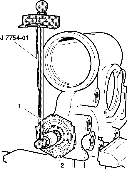
- Install J 7754-01
near vertical. Record the torque reading.
The torque reading should be 1.60 N·m (14 lb in)
while turning J 7754-01
in an arc 20 degrees left or right of the vertical position.
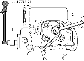
- With the steering gear
in the center position, loosen the preload adjuster nut (2). Ensure
the adjusting screw is backed out counterclockwise all the way.
- Turn the adjuster screw clockwise ½ turn. This prevents
the pitman shaft from bottoming out of the side cover.
- Place J 7754-01
in the vertical position in order to check the preload.
- Move J 7754-01
90 degrees to the left or the right of the center position. Record
the highest torque reading while moving J 7754-01
back to the center position.
- Tighten the adjuster screw clockwise until the torque reading
is 0.68-1.13 N·m (6-10 N·m) higher than
the reading taken in the previous step.
- Tighten the preload adjuster nut (2) to 90 N·m
(66 N·m). Ensure the adjuster screw does not turn during tightening.
- Reinspect the preload after tightening the preload adjuster nut (2).


