Valve Housing and Input Shaft Assemble TRW Ross
Tools Required
J 37612-A TAS65 Complete Tool Kit
- Lubricate all of the seals and the internal components with power steering fluid before assembly.
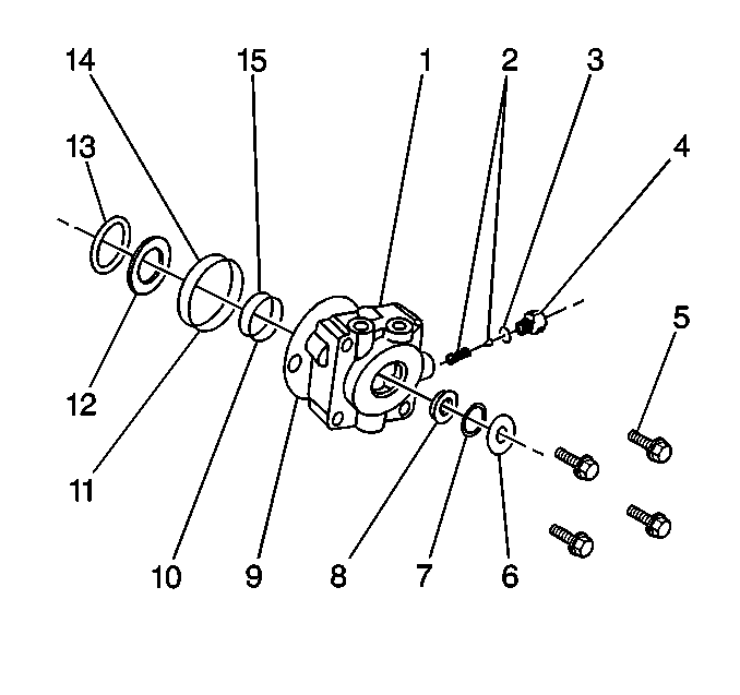
- Clamp the valve housing (1) in a vise so that the input shaft can be assembled vertically with the worm end up. Do not clamp against the threaded port hole or the relief valve hole sealing faces when placing the valve housing in a vise.
- Clean the valve housing counterbore of any foreign particles in order to ensure that the thrust washer will be squarely seated when assembled.
- Install the O-ring (10) into the counterbore in the valve housing (1).
- Install the O-ring (11) and the new seal (15) into the large diameter seal ring groove in the valve housing.
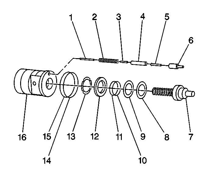
- Install the roller thrust bearing (13) onto the input shaft end of the input shaft.
- Install the thick thrust washer (12) onto the input shaft end of the input shaft.
- Seat the valve and worm assembly against the input shaft thrust face.
- Install the seal onto the input shaft (7) and against the thick thrust washer in order to hold the bearing components in place.
- Install the input shaft end of the assembly into the valve housing until the input shaft end is firmly seated.
- Dip the end of the input shaft worm assembly and the valve into oil up to the worm lead.
- Install the thrust bearing (8) followed by a thin thrust washer (9) over the ball groove end of the worm.
- Install the O-ring (11) into the seal groove in the bearing adjuster (12).
- Install the new seal into the same groove.
- Inspect the following components for dirt and staking burrs:
- Install the bearing adjuster over the worm and into the valve housing.
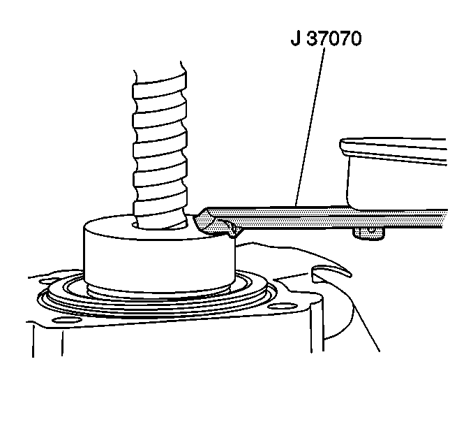
- Use the J 37070 in order to back the bearing adjuster off by ¼-½ turn.
- Reverse the assembly in the vise with the worm end facing down.
- Rotate the assembly in the vise.
- Use the J-37070, the J-37464 and J 37612-A in order to install the new jam nut with the radius side down.
- Inspect the input shaft torque.
- Repeat the tightening procedure as necessary.
- Use a suitable punch in order to stake the jam nut into the adjuster in one place at the threaded area. Choose areas that have not been previously staked.
Notice: When adding fluid or making a complete fluid change, always use the proper power steering fluid. Failure to use the proper fluid will cause hose and seal damage and fluid leaks.
| • | The valve housing |
| • | The adjuster jam nut |
| • | The bearing adjuster threads |
Notice: Use the correct fastener in the correct location. Replacement fasteners must be the correct part number for that application. Fasteners requiring replacement or fasteners requiring the use of thread locking compound or sealant are identified in the service procedure. Do not use paints, lubricants, or corrosion inhibitors on fasteners or fastener joint surfaces unless specified. These coatings affect fastener torque and joint clamping force and may damage the fastener. Use the correct tightening sequence and specifications when installing fasteners in order to avoid damage to parts and systems.
Tighten
Tighten the bearing adjuster to 17 N·m (13 lb ft).
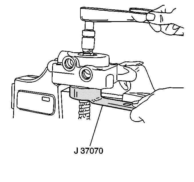
Use an inch-pound torque wrench on the input shaft.
Note the torque required in order to rotate the input shaft 360 degrees in each direction.
Tighten
Tighten the bearing adjuster in order to increase the maximum torque
at the input shaft 0.56-1.13 N·m (5-10 lb in).
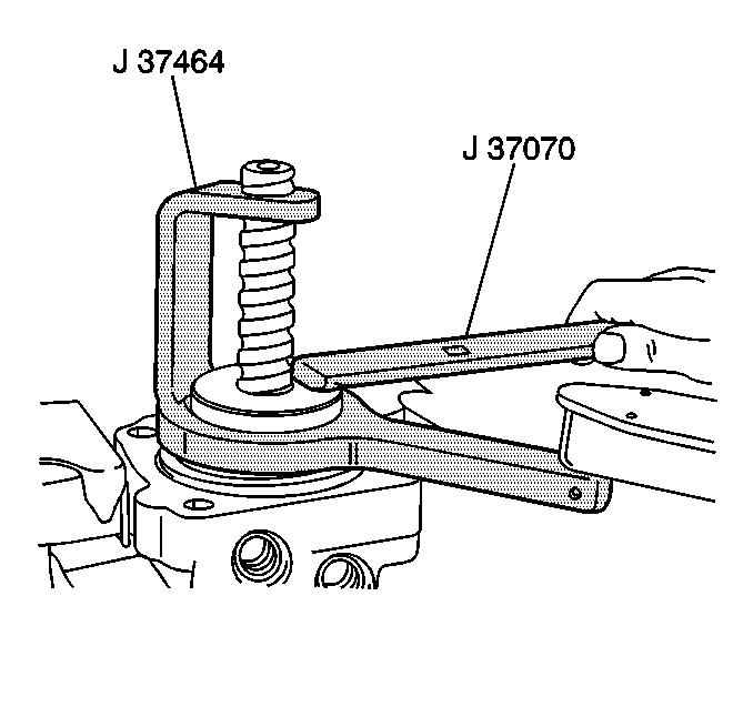
Tighten
Tighten the jam nut to 154 N·m (112 lb ft).
| • | The torque required in order to rotate the input shaft must be from 0.56-1.13 N·m (5-10 lb in) more than the original torque that was noted. |
| • | The torque required in order to rotate the input shaft must not be more than 2.5 N·m (22 lb in). |
| • | Unstake and adjust the components as necessary. |
