For 1990-2009 cars only
Disassembly Procedure
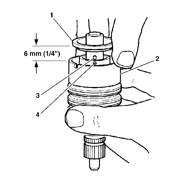
- Remove the stub shaft O-ring seal from the stub shaft cap end (1).
- Remove the stub shaft from the valve body (2).
- Tap the stub shaft lightly on a wood block in order to loosen the shaft cap.
- Pull the shaft cap and the valve spool out from valve body 6 mm (¼ inch).
- Disengage the stub shaft pin (3) from the hole in the valve spool (4).
- If the valve assembly needs repair, disassemble the valve as follows:
- Inspect the O-ring seals (2) and the valve body rings (2).
- If one or more of the following items occur, replace the valve assembly:
- If one or more of the following items occur, replace the stub shaft assembly (4) and the valve assembly:
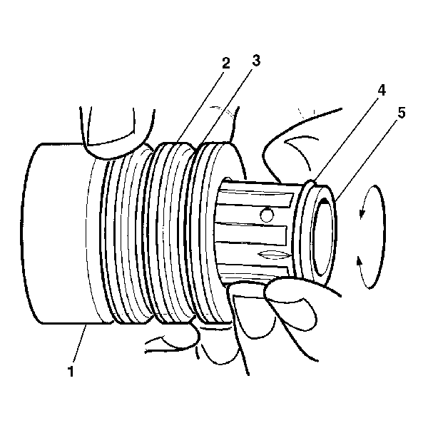
| 6.1. | Simultaneously pull and rotate the valve spool (5) in order to remove the valve spool (5) from the valve body (1). |
| 6.2. | Remove the valve spool O-ring seal (4). |
| 6.3. | Alternately remove the valve body valve body rings (2) and the O-ring seals (3). |
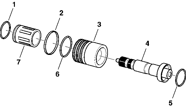
| • | The torsion bar and the stub shaft leak. |
| • | The ground surface of the stub shaft contains nicks or burrs. |
| • | The small notch in the skirt of the valve is worn. |
| • | The stub shaft pin contains wear or cracks. |
| • | The outside diameter of the valve spool contains nicks or burrs. |
| • | The inside diameter of the valve body contains nicks or burrs. |
| • | The valve spool (7) binds when rotated. |
Assembly Procedure
- Lubricate the new valve body ring (2) and the O-ring seals (3) with power steering fluid.
- Install the new O-ring seals (3) in the ring grooves.
- Install the new valve body rings (2) in the grooves over the O-ring seals (3).
- Lubricate the valve spool (5) and the valve spool O-ring seal (4) with power steering fluid.
- Install the valve spool O-ring seal (4) to the valve spool (5).
- Simultaneously push and rotate the valve spool (2) into the valve body (1) until the hole (3) in the valve spool (2) for the stub shaft pin is accessible from the opposite end of the valve body (1).
- Lubricate the stub shaft assembly (3).
- Install the stub shaft assembly (3) into the valve spool until the stub shaft pin can be place into the valve spool.
- Align the notch in the stub shaft cap (1) with the pin in the valve body (2).
- Install the valve spool and the stub shaft assembly into the valve body. The stub shaft cap should be below the valve body notch (1).
- Lubricate a new stub shaft cap to the stub shaft O-ring seal.
- Install the new stub shaft cap and the stub shaft O-ring seal into the valve body.

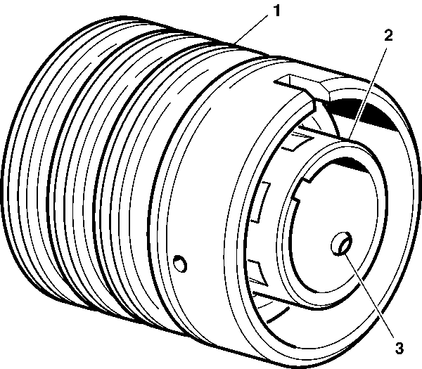
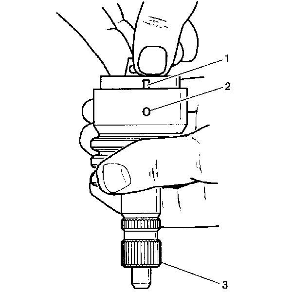
Important: Make sure that the shaft cap notch (1) is mated with the valve body pin before installing the valve body into the steering gear assembly.
