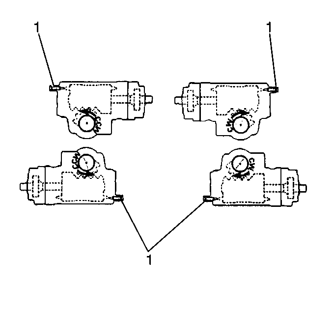
The TAS65 steering gears are equipped with
two hydraulic pressure relieving poppet valves.
The valves are automatically set to trip. The valve pressure is relieved
just before the steering stops are reached. The tripping is achieved after
the initial installation into the vehicle, at the first full right
and left turn.
The pressure relieving poppet valves will automatically reset themselves
if the steering stops are reset for increased steering gear travel. The valves
will reset themselves within the poppets adjustment limits, based
on acceptable equipment revisions from the original factory installations.
Readjust the poppet valves after installing the steering gear and adjusting
the poppet. Readjusting the poppet valves relieves hydraulic pressure at the
decreased steering gear travel.
Use the special service poppet adjusting screw kit in order to manually
adjust the poppet valves to the decreased steering gear travel.
The following conditions may result in further maladjustment of the
poppet valves:
Important: Steering stops should be adjusted such that a minimum of 1¾ steering
wheel turns from straight ahead position is available. If this is not possible,
the poppets are not functional nor can they be adjusted to function.
- Set the steering stops to the vehicle manufacturer's specifications.
Allow for the revisions from the original equipment installation.

- Turn the special service poppet adjusting screw (1) into the
non-sealing end of the service sealing jam nut until the drive end
of the screw is flush with the nut.
- Verify that the following conditions exist:
| • | The vehicle is unloaded. |
| | Important: With the road wheels in the straight ahead position, the steering gear
is in the center position when the timing marks on the end of the sector shaft
and housing trunnion are aligned.
|
| • | The wheels are in the straight ahead position. |
- Use a 5/8 in socket in order to remove the following components
from the lower end of the housing:
| • | The poppet fixed stop screw |
- Discard the screw and the washer.
Notice: Use the correct fastener in the correct location. Replacement fasteners
must be the correct part number for that application. Fasteners requiring
replacement or fasteners requiring the use of thread locking compound or sealant
are identified in the service procedure. Do not use paints, lubricants, or
corrosion inhibitors on fasteners or fastener joint surfaces unless specified.
These coatings affect fastener torque and joint clamping force and may damage
the fastener. Use the correct tightening sequence and specifications when
installing fasteners in order to avoid damage to parts and systems.

Important: The sector shaft may need to be moved slightly from the straight ahead
position in order to assemble the service adjusting screw (1) as instructed.
Return the sector shaft to the straight ahead position after
the assembly.
- Turn the screw (2) and the nut (3) assembly into the housing until the
nut is firmly against the housing.
Do not rotate the nut (3) on the screw (2).
Tighten
Tighten the sealing nut to 54 N·m (40 lb ft).
- Refill the pump reservoir with approved power steering fluid.

Important: Note which steering wheel rotation direction is required in order to
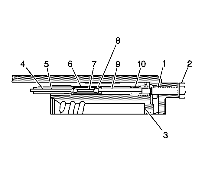
position the rack piston (3) toward the adjusting screw (1).
- Use the following steps in order to preset the upper poppet adjuster
seat and sleeve assembly:
| 8.1. | Observe the end of the sector shaft for direction of travel. Note
the direction of travel in order to position the rack piston (3) when the
poppets (9, 4) are reset. |
| 8.3. | Rotate the steering wheel in either the clockwise or the counterclockwise
direction. Locate the sector shaft toward the end of the steering travel. |
| 8.4. | Place the steering stop bolt against the steering stop in order
to position the rack piston toward the adjustable poppet screw (1) at the
closed end of the housing. |
| | Important: If excess input torque or rim pull is encountered at the steering wheel
prior to reaching the steering stop, allow the vehicle to roll slowly forward
while the steering wheel is being rotated.
|
| 8.5. | Continue to rotate the steering wheel until the following conditions
are met: |
| • | The steering stops are contacted. |
| • | A correct input torque is reached. |
| • | The initial internal engagement of the poppet adapter seat and
sleeve (5, 10) and the adjusting screw is felt. |
| • | There is a torque rise at the steering wheel. |
| 8.6. | Tighten the input torque. |
Tighten
Tighten the input torque of 54 N·m (40 lb ft)
at the steering wheel nut or 21.8 kg (48 lb) rim pull on a 508 mm
(20 in) steering wheel is reached.
- Turn the steering wheel at least 1¾ steering wheel
turns from the straight ahead position.
This action completes the internal preset of the upper poppet adjuster
seat and sleeve assembly (10).

- Loosen the sealing nut
(3).
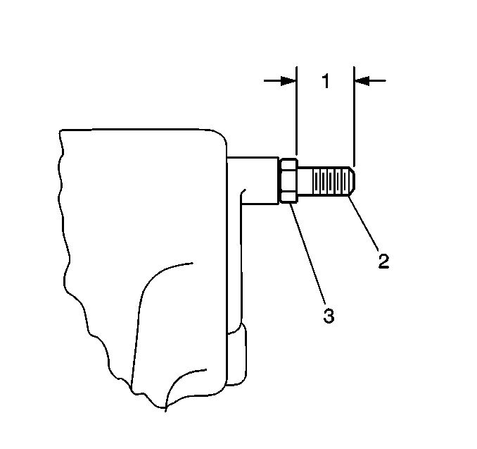
- Back out the adjusting screw (2) until 25.4-27.4 mm
(1.00-1.06 in) (2) of the screw (1) is beyond the sealing
nut (3).
- Torque the nut firmly against the housing. Maintain the clearance
of 25.4-27.4 mm (1.00-1.06 in).
Tighten
Tighten the sealing nut to 54 N·m (40 lb ft).
- Measure the adjusting screw (2).
Ensure that the adjusting screw (2) does not protrude more than 27 mm
(1.06 in) beyond the nut (1).
Important: If excess input torque or rim pull is encountered at the steering wheel
prior to reaching the steering stop, allow the vehicle to roll slowly forward
while rotating the steering wheel.
- Use the following steps in order to position the upper poppet valve
to the related axle stop:
| 14.1. | Ensure that the vehicle is unloaded. |
| 14.3. | Turn the steering wheel toward full travel in the opposite direction. |
| 14.4. | Turn the axle until the axle bottoms against the steering stop. |
Do not apply more than 33.9 N·m (25 lb ft)
or 13.6 kg (30 lb) rim pull on a 508 mm (20 in)
diameter steering wheel.
Notice: At no time should the system relief pressure be maintained for longer
than 5 seconds, as damage to the steering pump may result.

- Use the following steps
in order to return the system to the system relief pressure:
| 15.1. | Turn the steering wheel toward full travel in the opposite direction. |
Rotate the steering wheel until contact is made with the steering stop.
| 15.2. | Position the rack piston (3) toward the poppet adjusting screw
(1) at the closed end of the housing |
Important: Do not exceed the 2.3 N·m (20 lb in) maximum
torque increase on adjusting screw during step 10. Excessive screw torque
could upset the position of the poppets in the rack piston previously achieved
in order to control the upper poppet pressure relief. That would necessitate
the repetition of these entire procedures.

- Hold the steering wheel
in the steering stop contact position.
Loosen the sealing nut (3) one turn.
- Turn the adjusting screw (2) while holding the sealing nut (3).
Continue to turn the adjusting screw until the adjusting screw (2) torque
increases by 1.1-2.3 N·m (10-20 lb in).
- Back out the screw (2) by 4 turns.
- Release the steering wheel.
- Hold the adjusting screw in place.
Tighten the sealing nut (3) firmly against the housing.
Tighten
Tighten the sealing nut to 54 N·m (40 lb ft).
| | Caution: The 27 mm (1.06 in) maximum adjusting screw protrusion
from the sealing nut must not be exceeded to ensure adequate screw thread
engagement in housing. Inadequate screw engagement could cause loss of the
adjusting screw during operation. This could result in loss of power steering
and possible personal injury.
|
| 20.1. | If the adjusting screw extends more than 27 mm (1.06 in)
from the sealing nut, loosen the sealing nut. |
| 20.2. | Turn the adjusting screw until a length of 27 mm (1.06 in)
is achieved. |
| 20.3. | Tighten the sealing nut (3) again. |
Important: Repeat the adjustment procedure when the following conditions exist:
| • | The service adjustable poppet screw and the nut are in place. |
| • | The manual adjustment is complete. |
- For automatic adjustment, turn the adjusting screw into the nut in order
to duplicate the original fixed stop screw end position.


