For 1990-2009 cars only
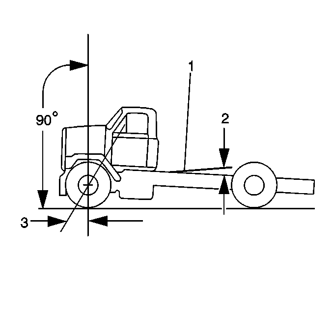
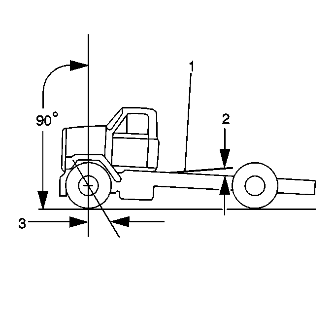
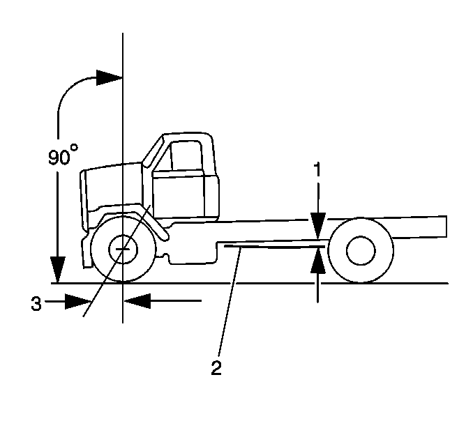
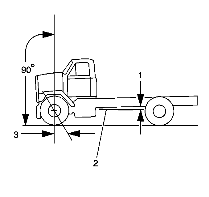
Caster dimensions are given for a vehicle carrying its design load equal to the capacity of the vehicle's suspension (GVWR). Perform alignment checks when the frame is level. If you make an alignment check when the frame is not level, determine the frame angle and add this angle to the caster angle, in order to obtain a true caster measurement. In order to determine the frame angle and the caster, complete the following steps:
- Place the vehicle on a smooth level surface.
- Measure the frame angle using a bubble protractor.
- Determine the caster angle for the left wheel using alignment equipment.
- Add or subtract the frame angle to or from the left wheel caster measurement in order to determine the correct caster for the left wheel.
- Determine the correct caster according to the following rules:
- Subtract the positive frame angle (2) from a positive caster measurement (3).
- Add the negative frame angle (1) to a positive caster measurement (3).
- Add the positive frame angle (2) to a negative caster measurement (3).
- Subtract the negative frame angle (1) from a negative caster measurement (3).
- Repeat steps 1 through 9 for the right wheel.
- Determine the specified caster by performing the following steps:
| • | The frame angle is the degree of tilt in the frame from the level position. |
| • | Negative frame angle, called Up in Rear, occurs when the frame is above level in the rear. |
| • | Positive frame angle, called Down in Rear, occurs when the frame is below level in the rear. |
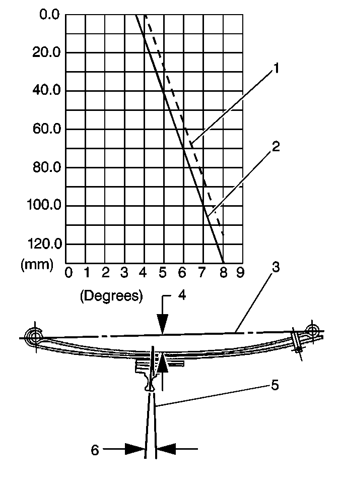
| 11.1. | Hold a taut string (3) between the centers of the spring eyes. |
| 11.2. | Measure the distance from the taut string to the top surface of the upper spring leaf, on a line that is perpendicular to the bottom of the frame rail (5) and at the centerline of the spring. Note the distance in millimeters from the centerline of the spring eyes to the top of the spring at the spring centerline (4). |
| 11.3. | Determine the specified caster angle using the graph (as shown). |
| 11.4. | Compare the specified caster angle with the measured caster angle. |
| 11.5. | If the specified caster angle does not coincide with the measured caster angle (plus or minus one degree), determine the cause of the error and replace the faulty component. |
