Diagnosis will be much easier once you have identified a vibration as first-order of driveline rotation during the road test. Next identify the exact area of the vibration and take proper action.
In most cases, vibration may be reproduced in the stall. In the stall the vibration may be better or worse than that experienced during the road test.
The objective is to reduce the vibration to the lowest point possible in the stall, then evaluate the results during a road test. Many times, a vibration you were only able to reduce drastically in the stall will be completely eliminated on the road.
The cause of first-order drive line vibration is usually excessive runout or an imbalanced component.
The following procedure offers a systematic process of elimination in order to determine which component is at fault:
- Raise the vehicle to curb height. Support the vehicle on a hoist or heavy stands. Refer to Lifting and Jacking the Vehicle in General Information.
- Remove the rear tire/wheel assemblies. Refer to Tire and Wheel Removal and Installation in Tires and Wheels.
- Remove the air drums. Refer to Brake Drum Replacement in Air Drums.
- Inspect the propeller shaft. The propeller shaft should be free of undercoating before continuing.
- Inspect the propeller shaft or U-Joint for any obvious dents or damage. Dents or damage will contribute to first-order driveline vibrations.
- Start the engine.
- Place the transmission in gear.
- Run the vehicle up to the speed at which the vibration was most severe. Do not step on the brake while the brake drums are removed.
- Record whether the vibration was present, and at what speed.
- If the vibration is not present, refer to First-Order Driving Vibration Testing (Torque Sensitive) in the Road Testing Diagnosis.
- If the vibration is present, determine which end of the driveshaft is vibrating the most. Hold your hand against the pinion nose and the transmission tailshaft, or hold an EVA vibration sensor up to each component.
- If the vehicle is equipped with a two-piece propeller shaft, inspect the center support bearing for vibration.
- If the transmission tail is vibrating, touch the transmission crossmember under the transmission mount. If there is no vibration on the crossmember, then the transmission mount is working properly.
- Remember which end of the driveshaft is the worst, and how severe the vibration is. The inspection will be a reference by which to judge future progress.
Do not fill the propeller shaft with foam, oil, or any other substance in order to correct a vibration. Filling the propeller shaft is only effective in reducing an unrelated condition called Torsional Rattle. Filling the propeller shaft should only be done in strict adherence to the procedure outlined in corporate bulletins that address Torsional Rattle. Failure to follow the correct procedure will induce a vibration and/or affect the structural integrity of the propeller shaft. The propeller shaft will then have to be replaced.
Propeller Shaft Runout
A propeller shaft or pinion (companion) flange with excessive runout causes first-order driveline vibrations. Use the following procedure in order to measure the runout of the propeller shaft:
| • | Remove excess corrosion of the propeller shaft surface before inspecting the runout. |
| • | Inspect for damage and dents. |
| • | Replace dented propeller shafts. |
| • | Remove any undercoating from the propeller shaft before proceeding. |
| • | Refer to Measuring Propeller Shaft Runout, below, for the measurement procedure that applies to the following shaft assemblies: |
| - | One-piece |
| - | Two-piece |
| - | Three-piece |
The splined end of a propeller shaft is critical to the smooth operation of a two-piece propeller shaft. When inspecting stub-shaft runout, ensure that the dial indicator readings are accurate.
Measuring Propeller Shaft Runout
Tools Required
| • | J 8001 Dial Indicator Set |
| • | J 7872 Magnetic Base Dial Indicator Set |
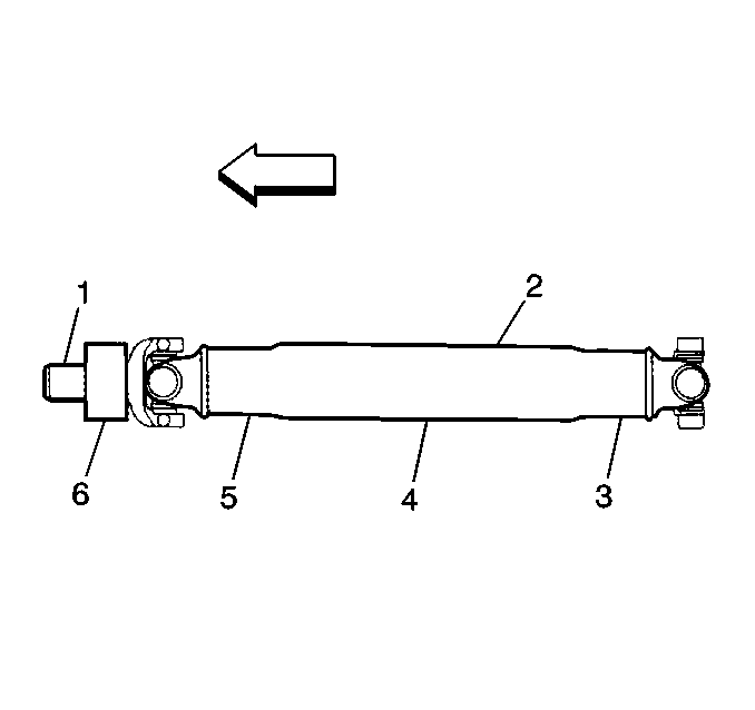
Important: When you replace a propeller shaft, inspect the new shaft for runout. Inspect the pinion flange runout if the replacement shaft runout is also out of tolerance.
Measuring Pinion Flange Runout
Tools Required
| • | J 8001 Dial Indicator Set |
| • | J 23409 Dial Indicator Extension |
| • | J 35819 Flange Runout Gauge |
- Place the vehicle on a suitable hoist. Refer to Lifting and Jacking the Vehicle in General Information.
- Allow the wheels to rotate freely.
- Remove the propeller shaft from the pinion flange.
- Install the J 35819 .
- Rotate the pinion shaft 360 degrees and zero the dial indicator on the low spot.
- Rotate the pinion flange again and record the total runout.
- If the pinion flange runout is 0.15 mm (0.006 in) or less, remove the pinion flange balance weight.
- If the pinion flange runout is greater than 0.15 mm (0.006 in) but not less than 0.28 mm (0.011 in), and the runout compensation weight is at or near the low spot, no further action is necessary. If the runout compensation weight is not at or near the low spot, remove the weight.
- If the pinion flange runout is greater than 0.28 mm (0.011 in) but not greater than 0.38 mm (0.015 in), and the balance weight is at or near the low point, no further action is necessary. If the runout compensation weight is not at or near the low spot, remove the weight and re-index the pinion flange until the runout is 0.25 mm (0.010 in) or less.
- Replace the pinion shaft when the runout is 0.25 mm (0.010 in) or less. Then, recheck the runout. Service replacement flanges do not have balance weights.
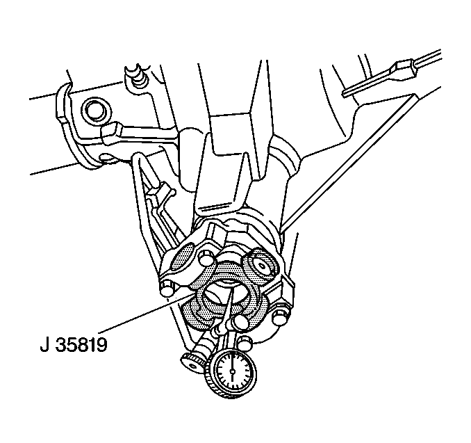
Important: The dial indicator will have inverted readings. You are measuring the inside diameter of the flange; you are not measuring the outside diameter. The highest reading on the dial indicator is the low spot. The lowest reading is the high spot.
Helpful Hints
| • | If J 35819 is not available, measure the pinion runout as close as possible to the pinion flange. |
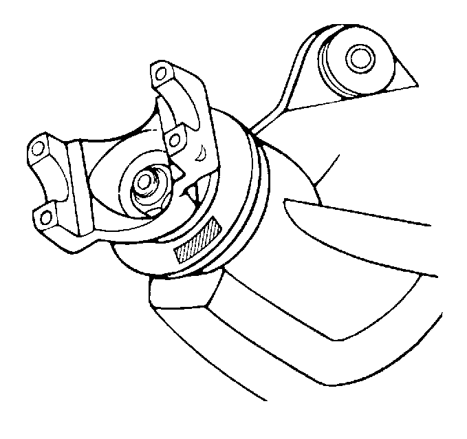
| • | If necessary, add compensation weights on the face of the pinion flange dust slinger. These weights are tack-welded onto the slinger. You may remove the weights with a die-grinder. |
| • | Carefully remove the spot weld at either end of the weight. |
| • | Do not remove the weight unless you have inspected the pinion flange runout and the procedure calls for weight removal. |
| • | Do not remove any weights on the outboard edge of the dust slinger. These weights are present in order to balance internal axle components. The weights are not related to the pinion flange runout. |
| • | If J 35819 is not available, inspect the propeller shaft runout as near as possible to the flange. Rotate the shaft 180 degrees in the pinion flange. Reinstall the shaft. Inspect the measurement at the same location. |
| A large difference in the runout, greater than 0.38 mm (0.015 in), may indicate that the flange is out of tolerance. If the runout does not change at all, the flange is OK. |
Balanced Axles
Beginning in the early 1990's, the manufacturer began system balancing rear axles. During the build process, these axle assemblies were spun with a slave fixture. A balance weight was attached to the outboard edge of the companion flange dust slinger. A system-balanced rear axle companion flange differs from a non-balanced flange. You must diagnose and service this flange in a unique way.
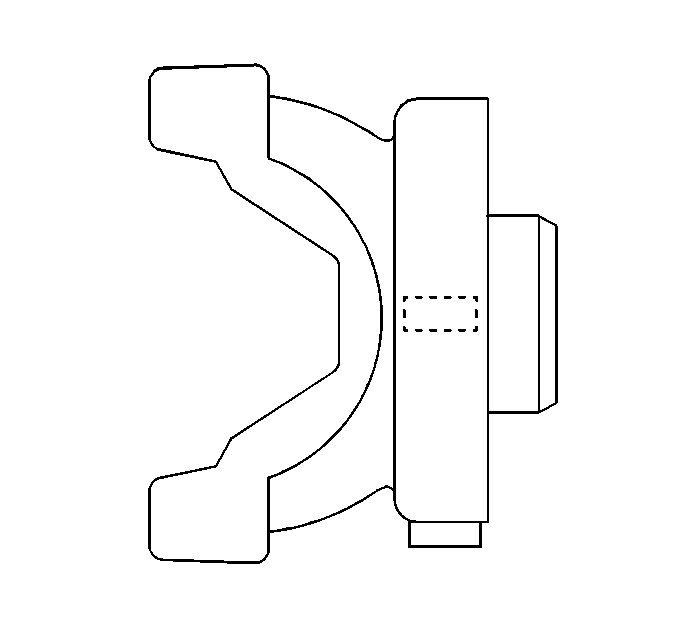
Some pinion flange assemblies have a U-shaped deflector designed to hold a system balance weight on the outside diameter.
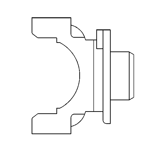
Other pinion flange assemblies have a runout compensation weight on the face of the deflector. The pinion flange assemblies that are system balanced do not use runout compensation weights.
Measuring the runout on a system-balanced companion flange is very straight-forward. A balanced flange that is good will have a measured runout between less than 0.38 mm (0.015 in). If a balanced flange has more than 0.38 mm (0.015 in) runout, replace the flange or reindex the flange 180 degrees on the pinion. If you replace or reindex a balanced flange, you must system balance the rear axle again.
Correcting Vibration at the Pinion Nose
Most first-order driveline vibrations originate at the pinion nose end of the driveshaft. Ensure that the vibrations are at a minimum at this location in order to achieve acceptable results. Reduce the runout of the components to a minimum. Balance the driveline as a system when necessary.
- Measure the runout of the propeller shaft and inspect the tolerance.
- If the tolerance is excessive, mark the position of the shaft for future reference and rotate the shaft 180 degrees.
- Reinstall the shaft and reinspect the runout. Inspect the level of vibration in order to determine if the vibration is lower or corrected.
- If the runout is still excessive, or if the vibration is still present, refer to Measuring Pinion Flange Runout. Replace the pinion flange or re-index the flange 180 degrees if the pinion flange runout exceeds the tolerance.
- Reinspect the propeller shaft runout if the vibration is present after the pinion flange runout is corrected. If the propeller shaft runout is still excessive, correct the runout before doing a driveline system balance. Either replace the shaft with a shaft that is within tolerance or sublet the shaft to a reputable independent for straightening and re-balance. Ensure that the new or rebuilt shaft is within runout tolerance before continuing.
- Once the propeller shaft and pinion flange are within runout tolerances, inspect to see if the vibration is still present. If the level of the vibration is still unacceptable, perform a driveline system balance procedure.
Remove and reinstall the pinion flange only once on axles utilizing a crush type sleeve. Replace the sleeve with a new sleeve if the sleeve is crushed. Removing the sleeve requires removal of the ring and pinion set. Replace flanges with excessive runout. Regardless of the method used, measure the pinion flange runout in order to ensure that the flange is within tolerance.
Correcting Vibration at the Transmission Tailshaft
First-order driveline vibrations that originate at the transmission end of the propeller shaft are rare. If the tailshaft of the transmission is vibrating, inspect the tailshaft housing bushing for wear or damage. A leaky transmission tailshaft oil seal indicates bushing problems.
Feel for vibration at the crossmember underneath the transmission mount. If there is no vibration, the transmission mount is functioning properly by isolating the vibration from the structure of the vehicle. The transmission mount is therefore probably not the cause of the vibration.
Use the following procedure if you can feel vibration on the crossmember and the tailshaft bushing, and if the transmission output is normal:
- Measure the propeller shaft runout. If the runout is excessive, replace the shaft with one that has acceptable runout. Alternatively, sublet the shaft to a reputable independent service shop in order to have the shaft rebalanced and the runout corrected.
- Test drive the vehicle. If the vibration is still unacceptable, balance the shaft on the vehicle. Refer to Rear Driveline System Balance.
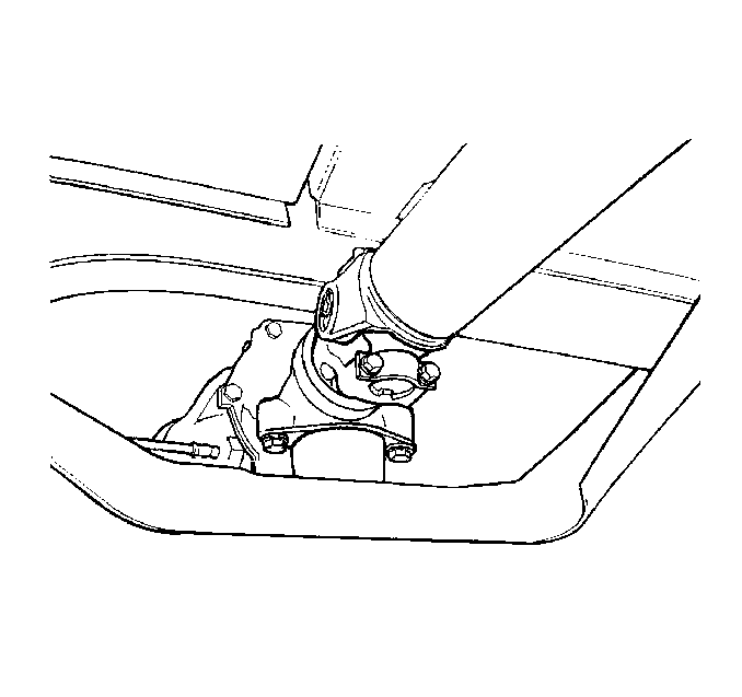
Correcting Vibration at the Center Support Bearing
These guidelines apply to the two-piece propeller shaft only. First-order driveline vibrations that occur mainly at the center support bearing are usually the result of excessive runout at the stub (splined) shaft.
Unlike other first-order driveline vibrations, these vibrations can appear at unusually low speeds of 40 km/h (25 mph) and up.
Perform the following procedure in order to correct this type of vibration:
- Mark the position of the rear propeller shaft at both ends for proper reassembly.
- Remove the rear propeller shaft from the vehicle.
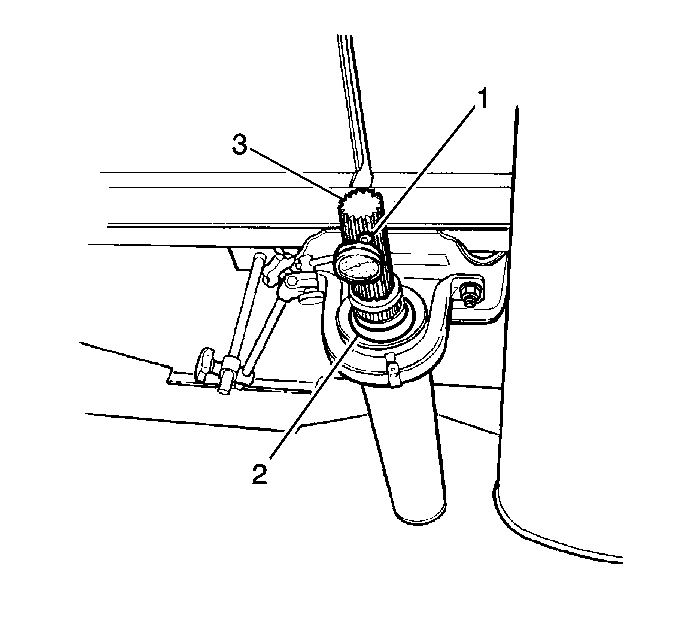
Correcting the stub shaft/spline runout will usually eliminate the vibration. If some residual vibration is still present, perform a road test on the vehicle. Determine if an on-vehicle system balance of the driveline is necessary.
Driveline System Balance without the Electronic Vibration Analyzer (EVA)
The following procedure is designed to fine-tune the balance of the propeller shaft while it is mounted in the vehicle. This procedure will also correct residual imbalance of the remaining driveline components.
Prior to balancing the driveline system, verify that the propeller shaft and the pinion flange runout are within specification.
Do not overheat the engine when performing this procedure.
- Raise the vehicle to curb height. Support the vehicle on a hoist or on safety stands. Do not allow the axle to hang. Refer to Lifting and Jacking the Vehicle in General Information.
- Remove the rear tire/wheel assemblies. Refer to Tire and Wheel Removal and Installation in Tires and Wheels.
- Remove the air drums. Refer to Brake Drum Replacement in Air Drums.
- Determine which end of the propeller shaft has the most vibration in order to identify where to begin installing the hose clamps.
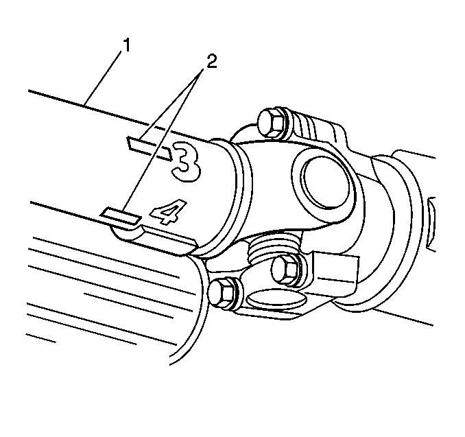
The following procedure uses a trial and error method of determining where to place the hose clamps on the shaft. Use the following tips in order to help locate the clamps:
- Because the imbalance may be related to propeller shaft runout, begin installing the clamps at the low point of the propeller shaft runout.
- When the plant workers balance the propeller shaft, weights are used in graduated increments: 1/16 oz, 1/8 oz (1.75 g, 3.5 g), etc. If the stock weight is too light or too heavy, place the hose clamp either directly in line with or opposite to the stock weight.
The last method involves running the vehicle at a speed which the vibration is felt.
- Carefully hold a piece of chalk up to the very end of the propeller shaft. Barely touch the chalk to the shaft.
- Shut the engine OFF in order to stop the propeller shaft from rotating. Do not step on the brake pedal. Do not put the transmission in PARK.
- Inspect the chalk mark.
If you performed the above procedure correctly, the chalk mark will indicate the heavy spot on the shaft. The heavy spot will deflect downward and touch the chalk. If the chalk mark circles the entire shaft, touch the chalk more gently to the shaft. Ensure that the chalk touches only the heavy spot. Once the heavy spot is located, place the hose clamp 180 degrees opposite to the chalk mark. Perform the following steps:
Continue the trial and error procedure using different weights in different locations until you achieve the best balance. If more that 3 clamps aligned in the same position are required, replace the propeller shaft.
If you are able to reduce the vibration in the stall, but are unable to eliminate the vibration completely, perform a road test on the vehicle. A slight vibration noticeable in the stall may not be noticeable on the road.
Driveline System Balance with Electronic Vibration Analyzer (EVA)
In order to pinpoint the source, you must reproduce the vibration in the service stall. Determine which component is vibrating the most using the EVA. Perform the following steps:
- Support the vehicle on a suitable hoist or on safety stands. Ensure that the rear of the rear axle is at curb height. Do not allow the axle to hang. Refer to Lifting and Jacking the Vehicle in General Information.
- Remove the rear tire/wheel assemblies. Refer to Tire and Wheel Removal and Installation in Tires and Wheels.
- Remove the air drums. Refer to Brake Drum Replacement in Air Drums.
- Ensure that the propeller shaft is free of undercoating. Check for dents or damage to the propeller shaft or U-Joint.
- Start the engine.
- Place the transmission in gear.
- Run the engine at the vehicle speed at which the vibration is occurring.
Caution: Do not run the vehicle higher than 89 km/h (55 mph). Stay clear of the universal joints and the balance weight area in order to avoid personal injury. Do not run the vehicle on the hoist for extended periods of time. Running the vehicle on the hoist for extended periods of time may cause the engine or the transmission to overheat.
Determine which end of the propeller shaft is vibrating the most. Hold the EVA's sensor against the pinion nose and the transmission tailshaft assembly. The higher the amplitude reading, the greater the vibration.
| • | If the vehicle has a two-piece propeller shaft, inspect the center support bearing. |
| • | If the transmission tailshaft vibrates, inspect the transmission crossmember under the transmission mount. The vibration should not be present if the mount is functioning correctly. |
Strobe Balance Testing with the Electronic Vibration Analyzer (EVA)
Ensure that the runout of the various driveline components are within specifications. If the runouts are within specifications, strobe balance the driveline. The EVA is able to simplify the balancing process, using the following procedure:
- Use the EVA in order to determine which end of the propeller shaft has the most vibration.

If the shaft will not balance using 2 weights, place a third weight on the light spot. Split the first 2 weights in order to produce a total weight between 2 and 3 weights.
If 3 weights fail to balance the driveline, replace the propeller shaft.
When the propeller shaft balances, road test the vehicle in order to verify that the vibration is eliminated.
Propeller Shaft Balance Weights
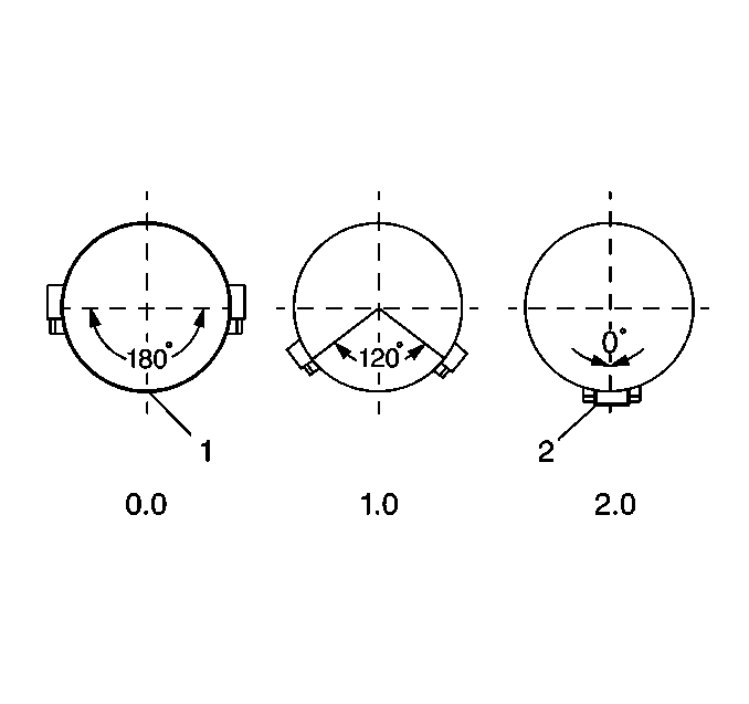
When using clamps in order to balance a propeller shaft with the total weight method, the correction weight required will often be a fraction or a multiple of one hose clamp. Use the following phasing procedure with 2 hose clamps in order to accurately place any required amount 0-2 weights (0.0-2.0 total weights).
- Ensure that the clamps are located with even spaces on either side of the light spot, or 180 degrees opposite the heavy spot.
- If the vibration does not change at all or gets worse, then 1 clamp is too light or too heavy. Repeat the procedure using the 2 clamps together.
- If the previous step did not correct the problem, repeat the procedure using the 2 clamps separated in order to reduce the spinning weight.
- Continue the trial and error procedure using different weights in different locations until you achieve the best balance.
- If more than 3 clamps aligned in the same position are required, replace the propeller shaft.
- If you are able to reduce the vibration in the stall, but are unable to eliminate the vibration completely, road test the vehicle. A slight vibration noticeable in the stall may not be noticeable on the road.

| (1) | Balance Location |
| (2) | Clamps Together |
The table containing the weight amounts in terms of the total weight and the included angle (spread) between the clamps is in specifications. Refer to Specifications.
First-Order Driveline Vibration Analysis (Torque Sensitive)
If the following conditions are true, the internal rear axle components are the probable cause of the vibration:
| • | If the vehicle has a vibration that is equal to first-order driveline rotation, and the vibration is not present when testing the vehicle in the stall |
| • | If you were able to correct the vibration in the stall, but the vibration returned during the road test |
Internal rear axle vibrations may be aggravated by the load of the vehicle working against the ring and pinion gear seat.
Since the propeller shaft and the pinion gear are bolted together through the pinion flange, the propeller shaft and the pinion gear operate at the same speed. Vibration in the pinion gear will therefore have the same frequency and symptoms as the propeller shaft.
In order to isolate the vibration to the pinion gear, use the following procedure:
- Raise the vehicle to curb height. Support the vehicle on a hoist or on safety stands. Refer to Lifting and Jacking the Vehicle in General Information.
- Remove the tire/wheel assemblies. Refer to Tire and Wheel Removal and Installation in Tires and Wheels.
- Remove the air drums. Refer to Brake Drum Replacement in Air Drums.
- Touch the pinion nose or hold the EVA vibration sensor up to the pinion nose.
- With the aid of another technician, accelerate and decelerate the vehicle through the speed range at which the vibration was noticed during the road test.
Example
| • | If the vibration was originally noticed at 88 km/h (55 mph), accelerate from 72 km/h (45 mph) to 107 km/h (65 mph). Then decelerate from 107 km/h (65 mph) back to 72 km/h (45 mph). |
| • | Repeat the above step and remember whether or not the pinion nose vibrates under load during acceleration and/or deceleration. |
If the vibration does not occur during the above procedure, install the brake drums and the tire/wheel assemblies, adding additional load on the system. Then repeat the above test.
Ensure that both axle shafts rotate at the same speed. The differential may mask a vibration when one tire is spinning faster than the other tire. Adjust the brakes in order to correct unequal tire rotation speed.
If you are unable to reproduce the vibration in the stall, apply the brake lightly in order to load the system further. Maintain the vehicle speed at which the vibration was noticed. Do not overheat the brakes.
If the pinion nose vibrates under acceleration and/or deceleration, and the other driveline components are eliminated as the cause of the vibration, then one of the following conditions may cause the vibration:
| • | A high spot on the pinion gear |
| • | A bent pinion stem |
| • | A cocked pinion bearing |
| • | An improper axle housing bore |
Anything that effects the pinion gear and how the pinion gear contacts the rotating ring gear may contribute to a first-order, torque-sensitive driveline vibration. The only way to correct the condition is to replace the faulty components. In most cases, you must replace the ring and pinion gear set and the related bearings. In some cases, you must replace the axle housing. Complete a close-up visual inspection for damage or unusual wear in order to measure or identify the specific faulty component.
It is possible to isolate an internal axle vibration. Install a known good axle assembly from a stock unit. Verify that the known good axle assembly does not have a vibration problem.
Once you correct the internal axle problem, road test the vehicle. Inspect the vehicle for vibration. Balance the driveline, as necessary, in order to eliminate any remaining vibration.
