Side to Side Strg Wheel Movement/Bump steer (Install Leaf Spring Spacer/U-bolts)

| Subject: | Side to Side Steering Wheel Movement/Bump Steer (Install New Front Leaf Spring Spacer and U-bolts) |
| Models: | 1997-2000 Chevrolet and GMC B7 Medium Duty School Bus Models |
| With 10,000# Front Axle, 11,000# Front Suspension and Ross Power Steering (RPOs FM6, FNO, NXW) |
Condition
Some drivers may comment about a back and forth rocking movement of the steering wheel. This condition is especially noticeable when the vehicle travels on an irregular road surface and/or when driving over dips in the road. This condition may also be known as bump steer.
Cause
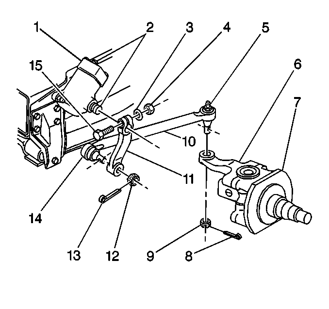
The steering system geometry may contribute to this condition, resulting in a variance in ball height at the steering knuckle third arm (6).
As the vehicle travels over dips or irregularities in the road surface, the jouncing of the front leaf spring may cause a tug on the pitman arm. This may result in the side to side movement of the steering wheel.
Correction

Install a 20 mm (0.80 in) spacer between the front axle and both front leaf springs on vehicles that may exhibit this condition. This spacer moves the pitman arm and the steering knuckle ball (5) 20 mm (0.80 in) further apart. The relay rod (10) angle will also change as a result of the spacer installation. This spacer creates different steering geometry that should reduce the potential for a tug on the pitman arm (11).
The spacer installation will also require longer spring U-bolts. Use the following procedure and the part numbers listed below.
- Set the parking brake.
- Block the rear wheels.
- Place a jack under the front axle and raise the vehicle. Support the vehicle by placing suitable safety stands under the frame.
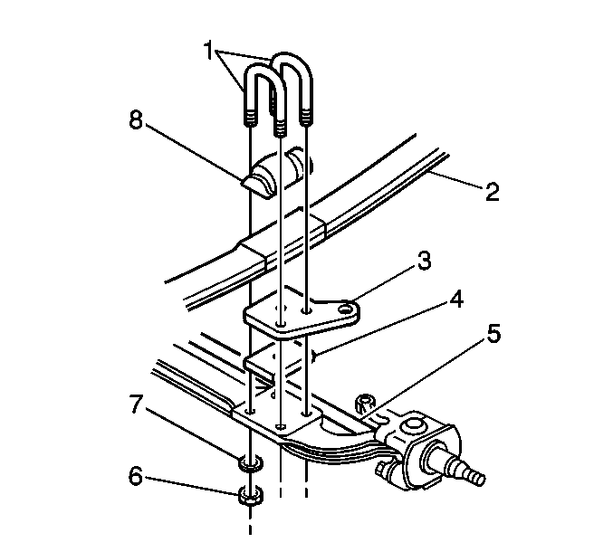
- Remove the spring U-bolt nuts (6) and the washers (7).
- Remove the spring U-bolts (1) from the vehicle.
- Lower the axle (5) far enough to provide clearance between the axle and the lower shock mounting bracket (3).
- Install the spacer (4) between the lower shock mounting bracket and the axle. Ensure that the spring stud seats securely into the spacer.
- Install the new spring U-bolts.
- Install the new spring U-bolt washers and the nuts.
- Remove the safety stands.
- Lower the vehicle.
Notice: Do not use the front crossmember to support the vehicle or the crossmember may buckle.

Notice: Use the correct fastener in the correct location. Replacement fasteners must be the correct part number for that application. Fasteners requiring replacement or fasteners requiring the use of thread locking compound or sealant are identified in the service procedure. Do not use paints, lubricants, or corrosion inhibitors on fasteners or fastener joint surfaces unless specified. These coatings affect fastener torque and joint clamping force and may damage the fastener. Use the correct tightening sequence and specifications when installing fasteners in order to avoid damage to parts and systems.
Tighten
Tighten the nuts to 350 N·m (258 lb ft).
Parts Information
Part Number | Description | Qty |
|---|---|---|
15153701 | Spacer Asm. - Frt Spring Lwr (20 mm) | 2 |
15983090 | U-bolt - Frt Spring | 4 |
11516202 | Nut - U-bolt | 4 |
15650968 | Washer - U-bolt | 4 |
Parts are currently available from GMSPO.
Warranty Information
For vehicles repaired under warranty, use:
Labor Operation | Description | Labor Time |
|---|---|---|
E3240/E3241 | U-bolt, Front Spring - Replace (Right and Left) | Use published labor operation time |
In Other Labor Hours, add 0.4 hr for installing the left and right spacer. | ||
