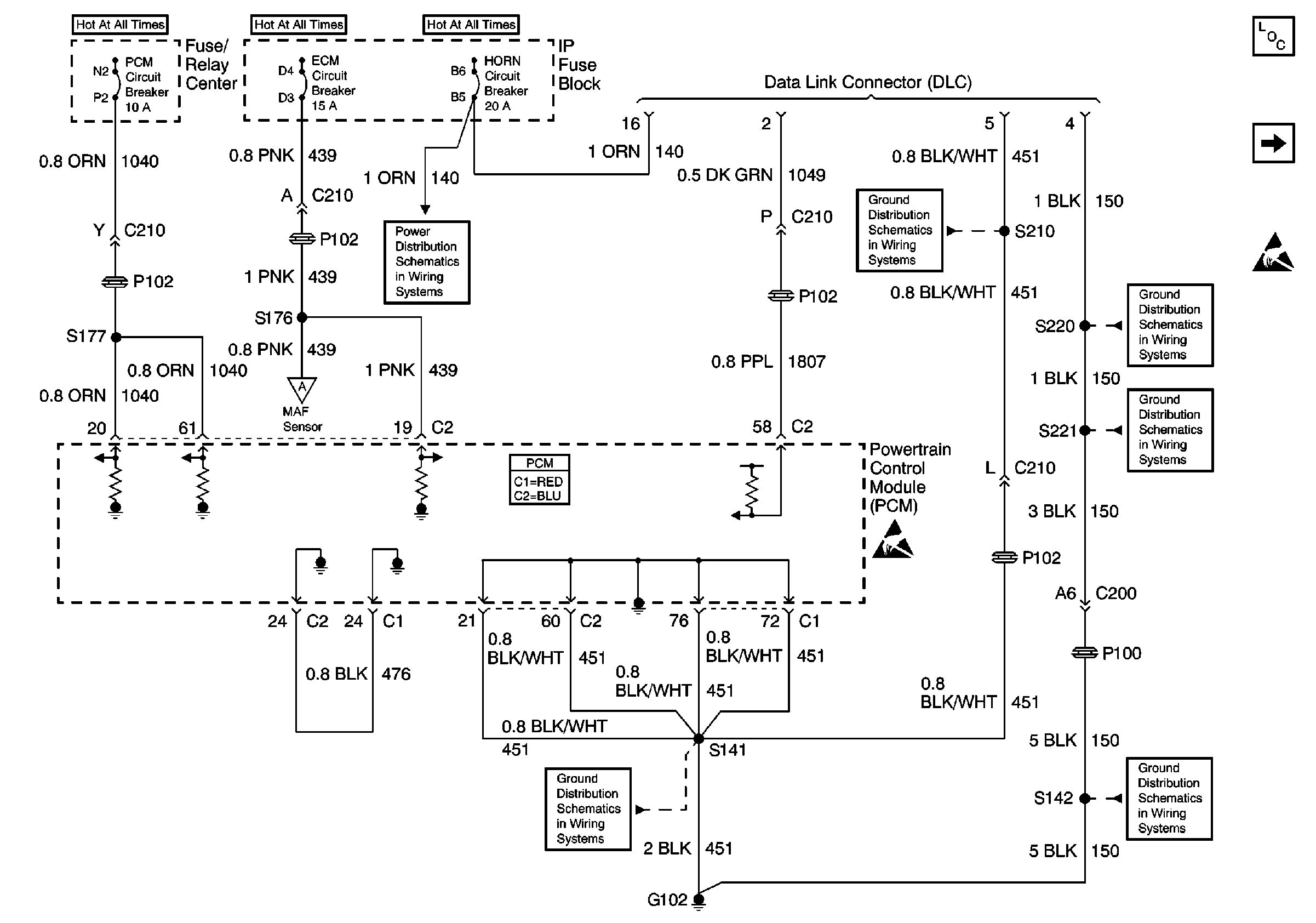
| Figure 1: |
DLC, PCM Power and Ground
|
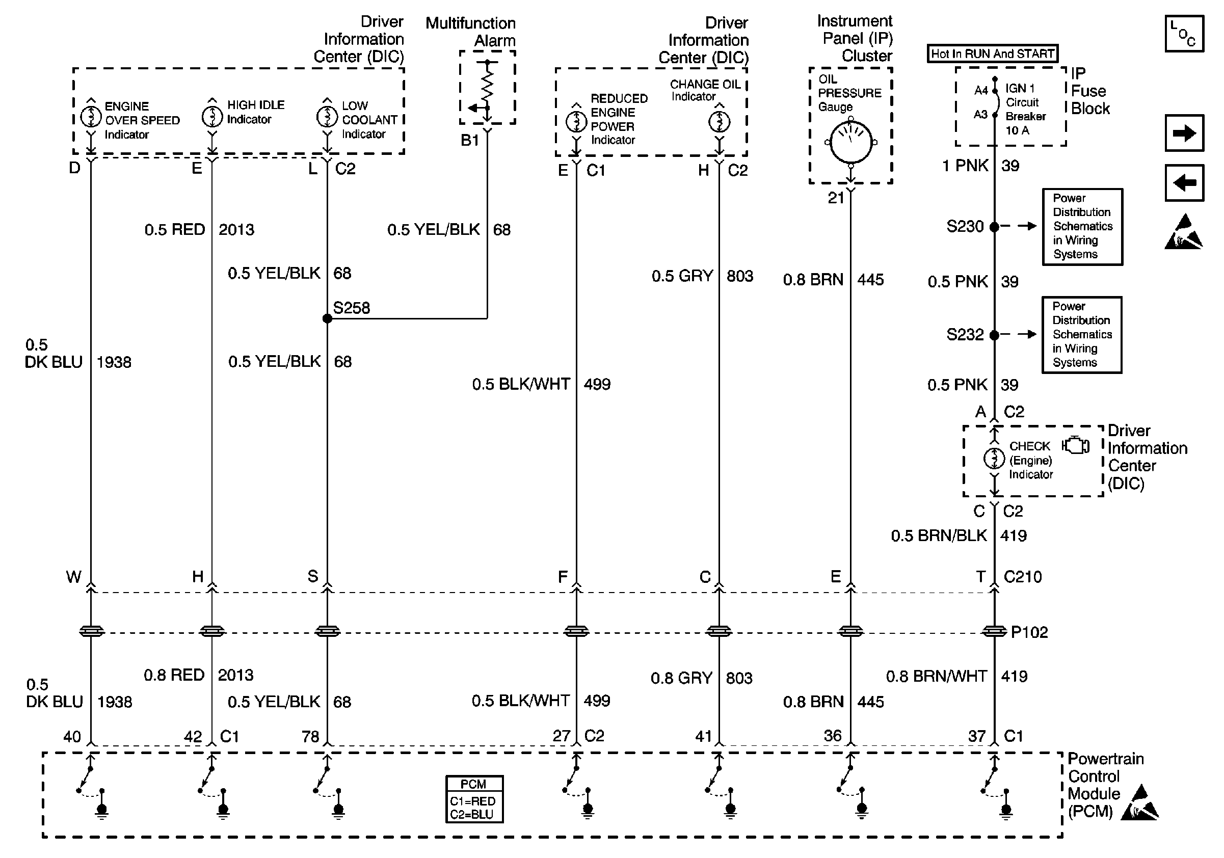
| Figure 2: |
Indicators
|
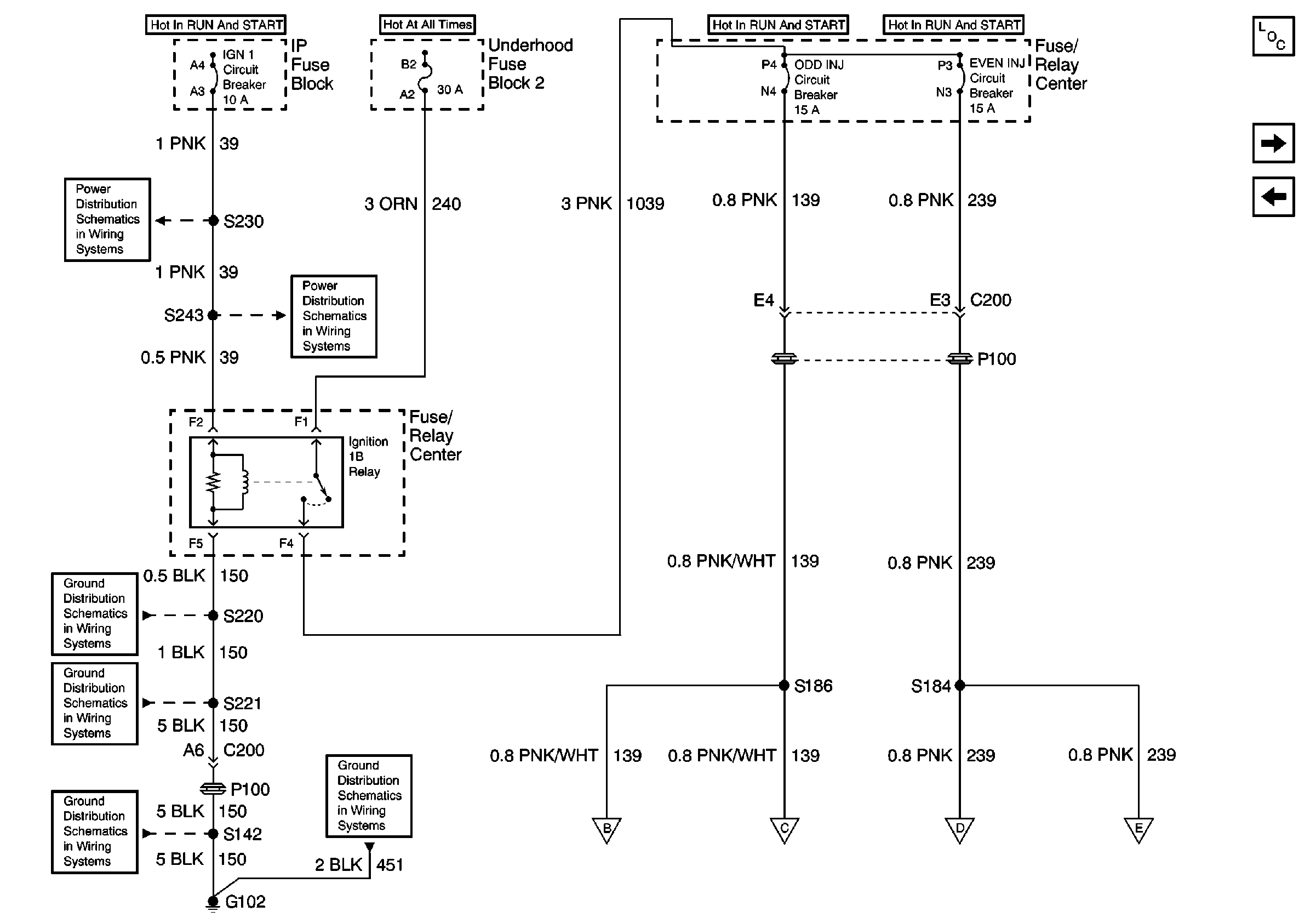
| Figure 3: |
Power Distribution for Coils and Injectors
|
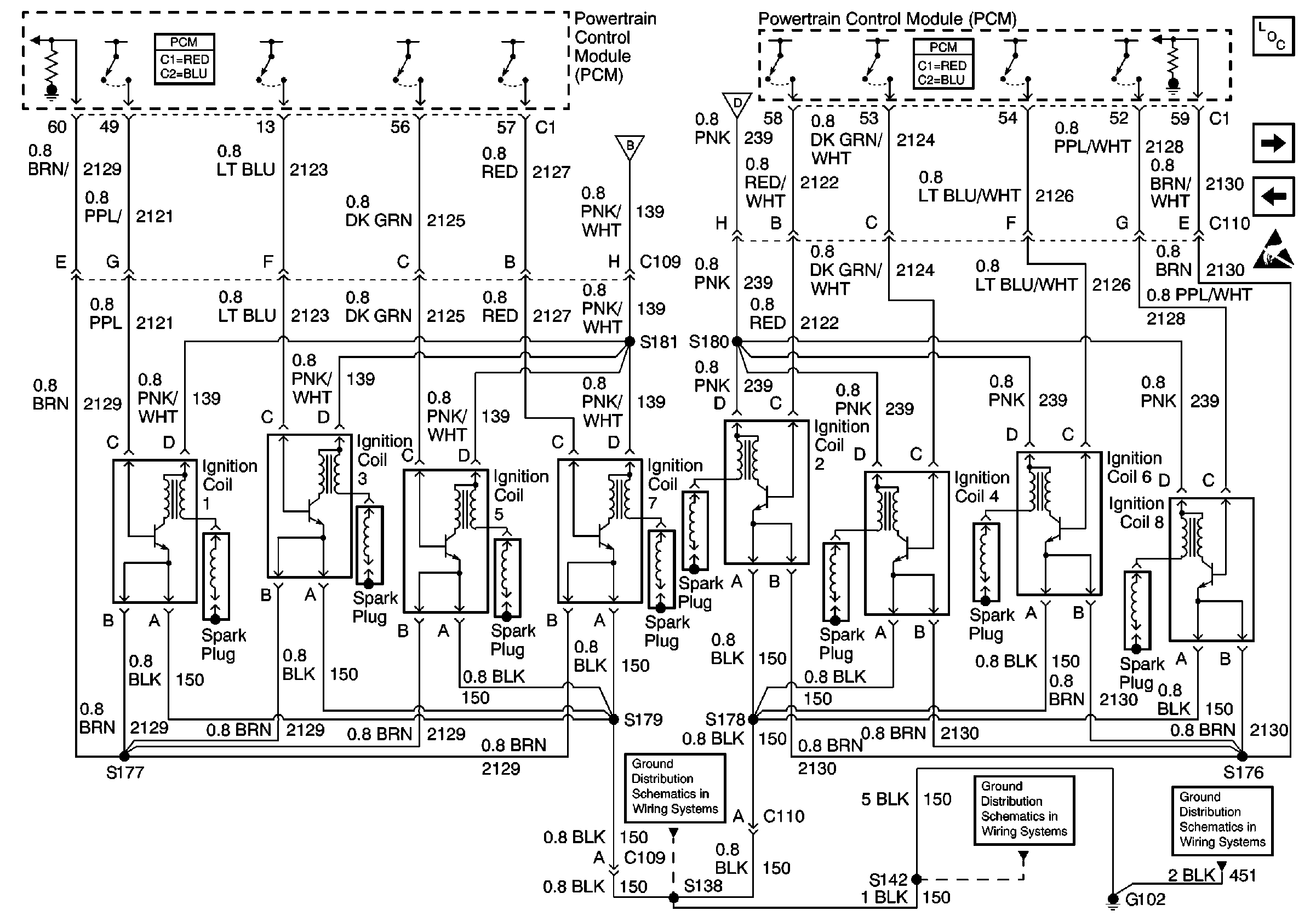
| Figure 4: |
Ignition Coils
|
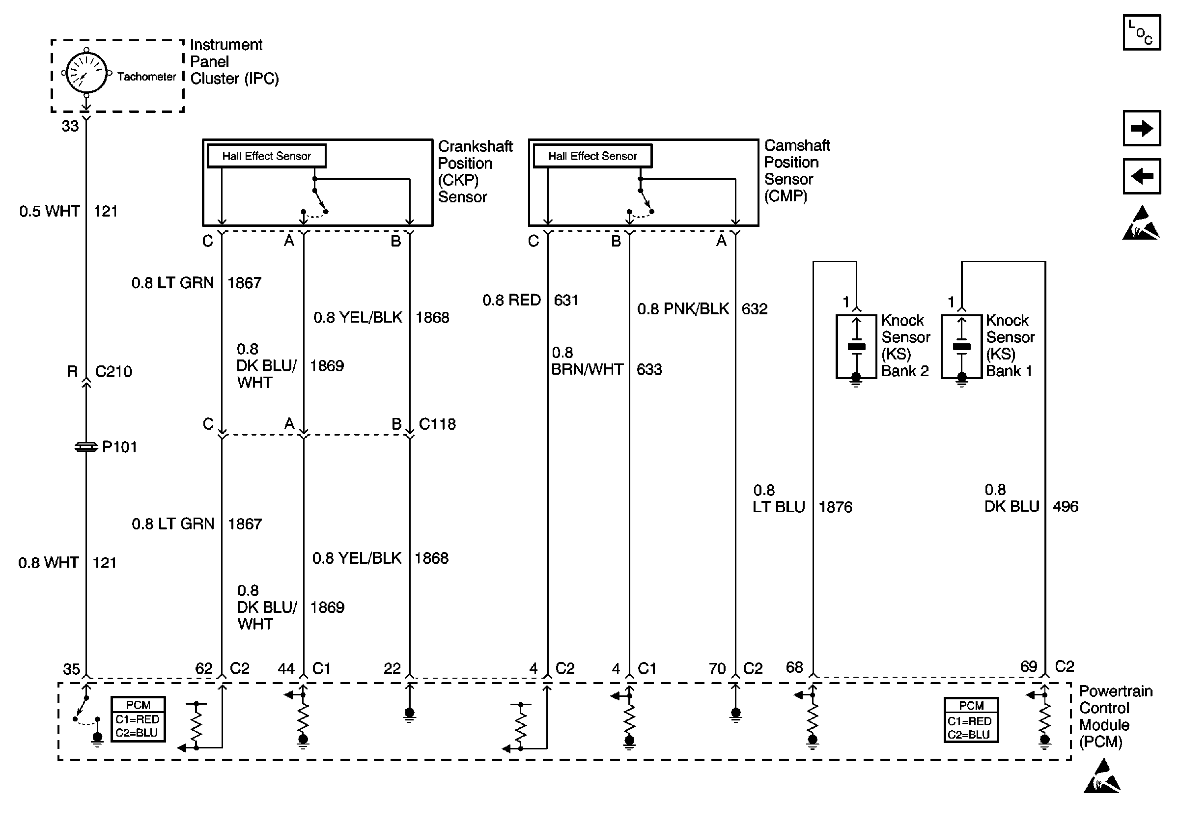
| Figure 5: |
CKPand CMP Sensors, KS and Tachometer
|
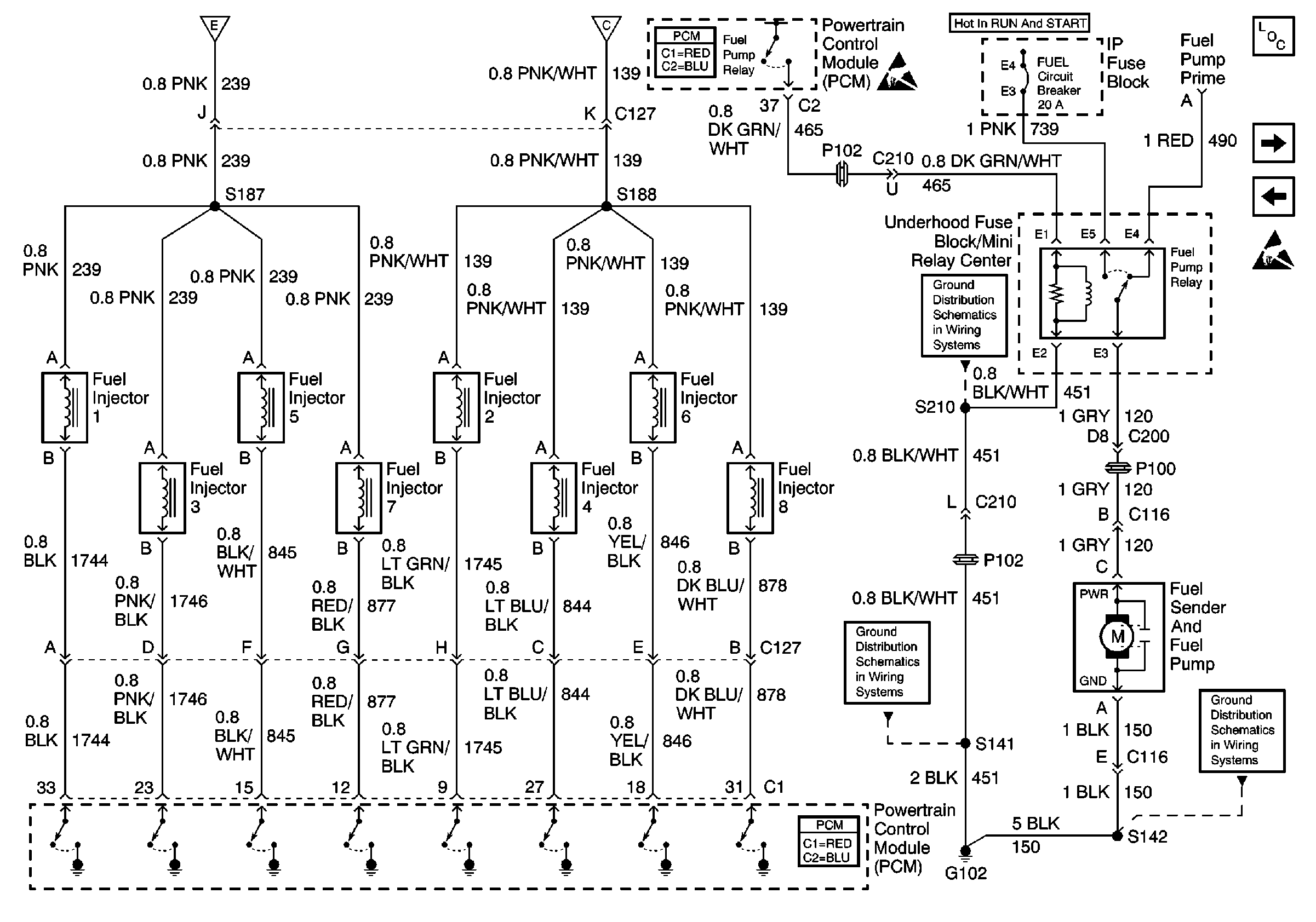
| Figure 6: |
Fuel Enable and Feul Injectors
|
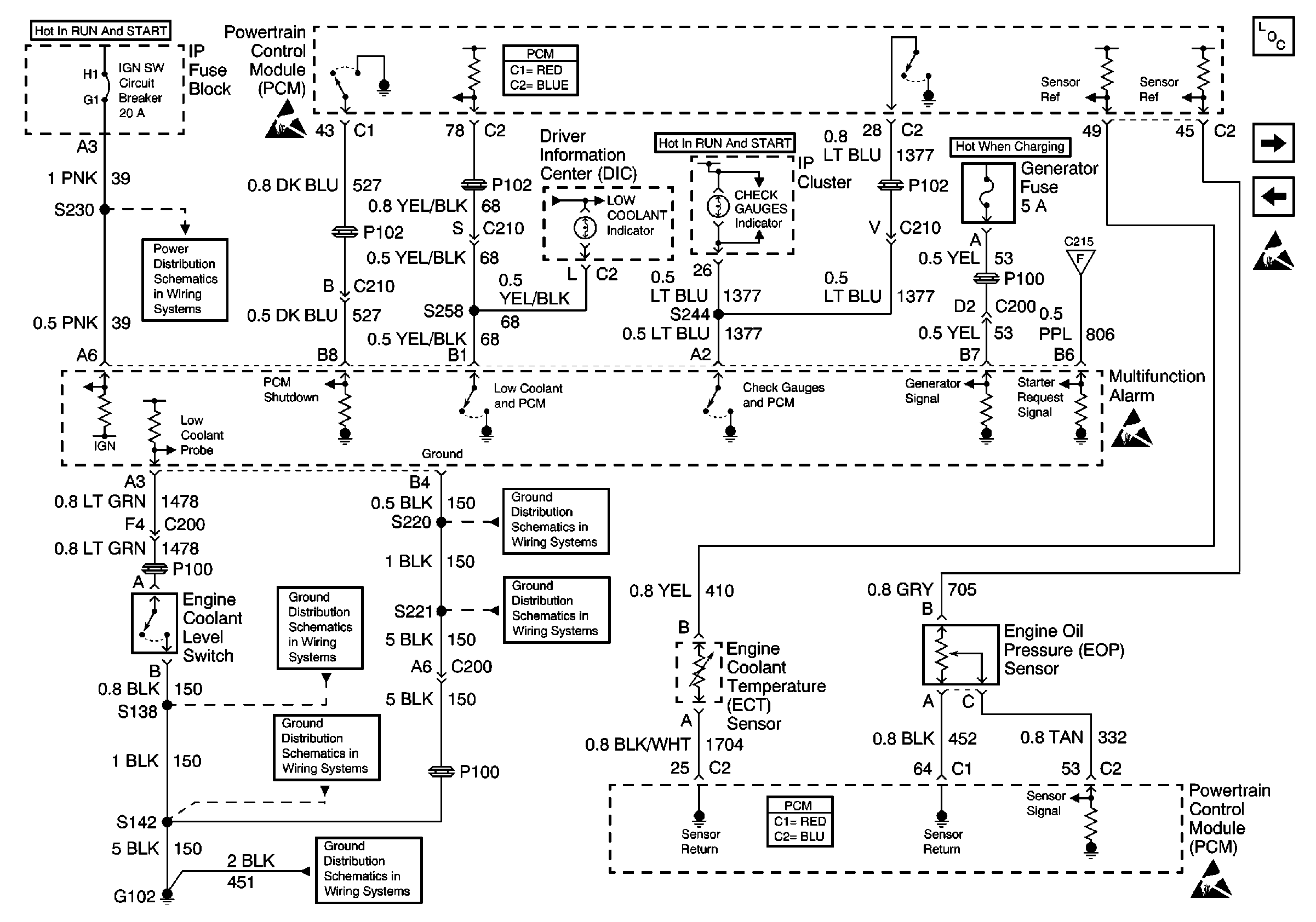
| Figure 7: |
Automatic Engine Shutdown and Warning
|
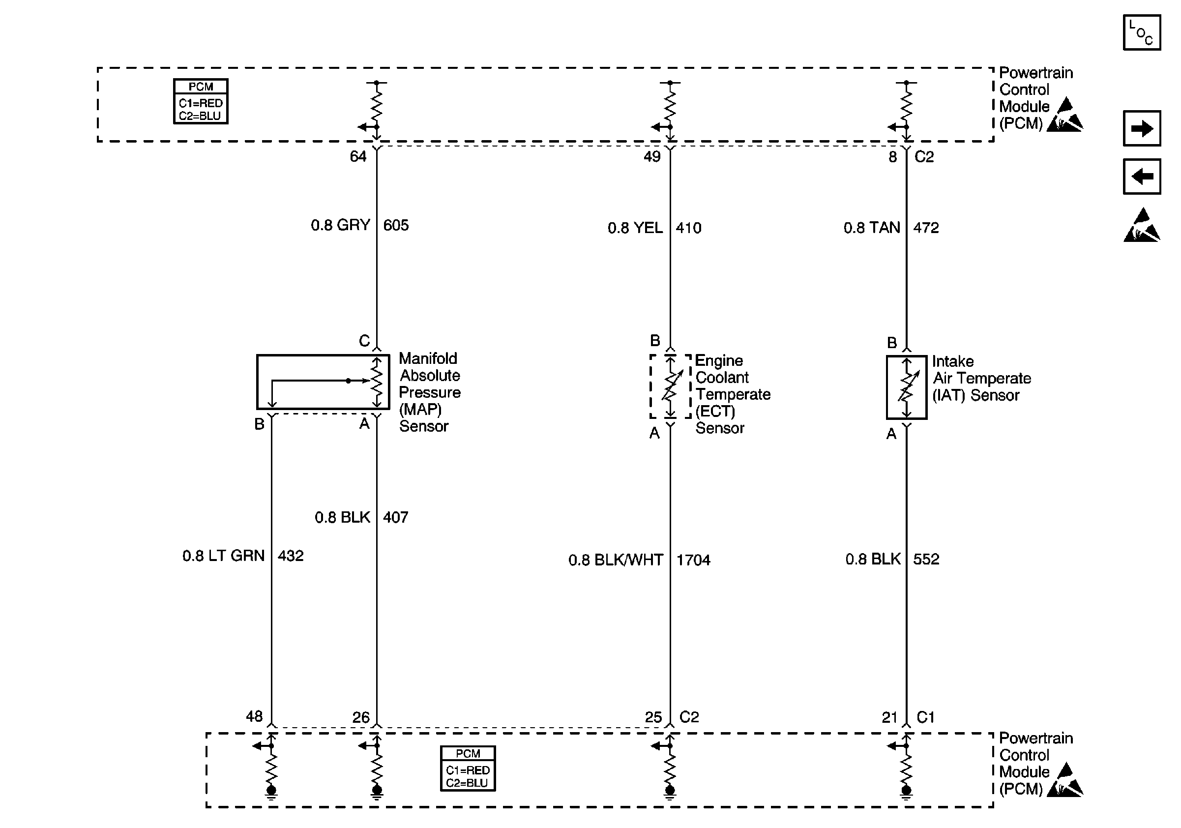
| Figure 8: |
ECT, IAT, and MAP Sensors
|
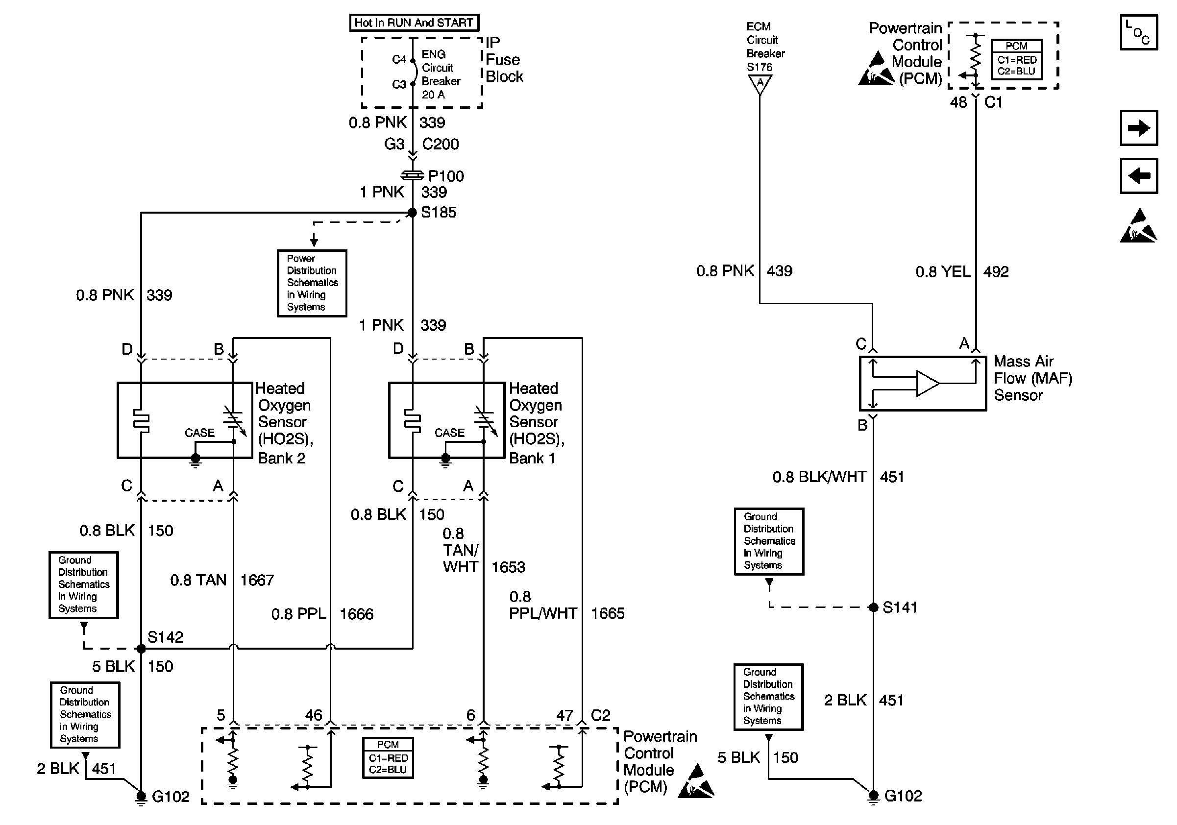
| Figure 9: |
HO2S and MAF Sensor
|
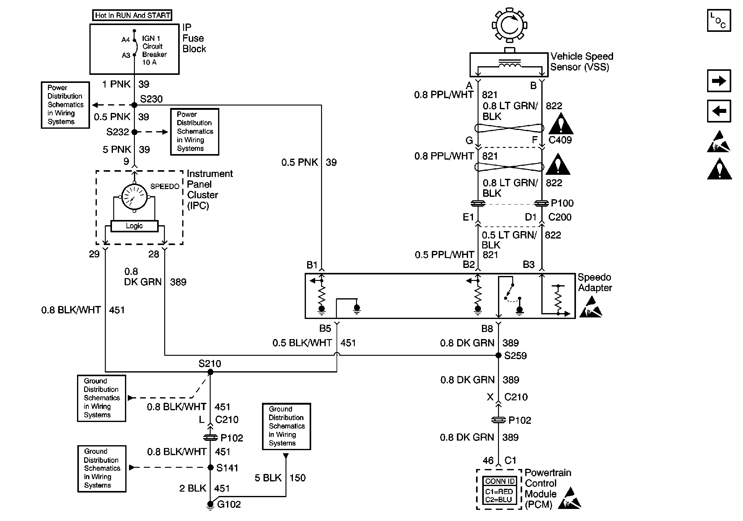
| Figure 10: |
VSS
|
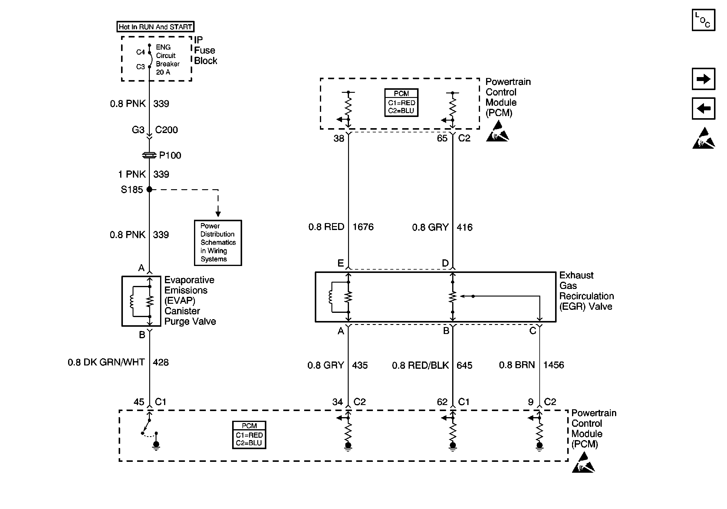
| Figure 11: |
EGR and EVAP Valves
|
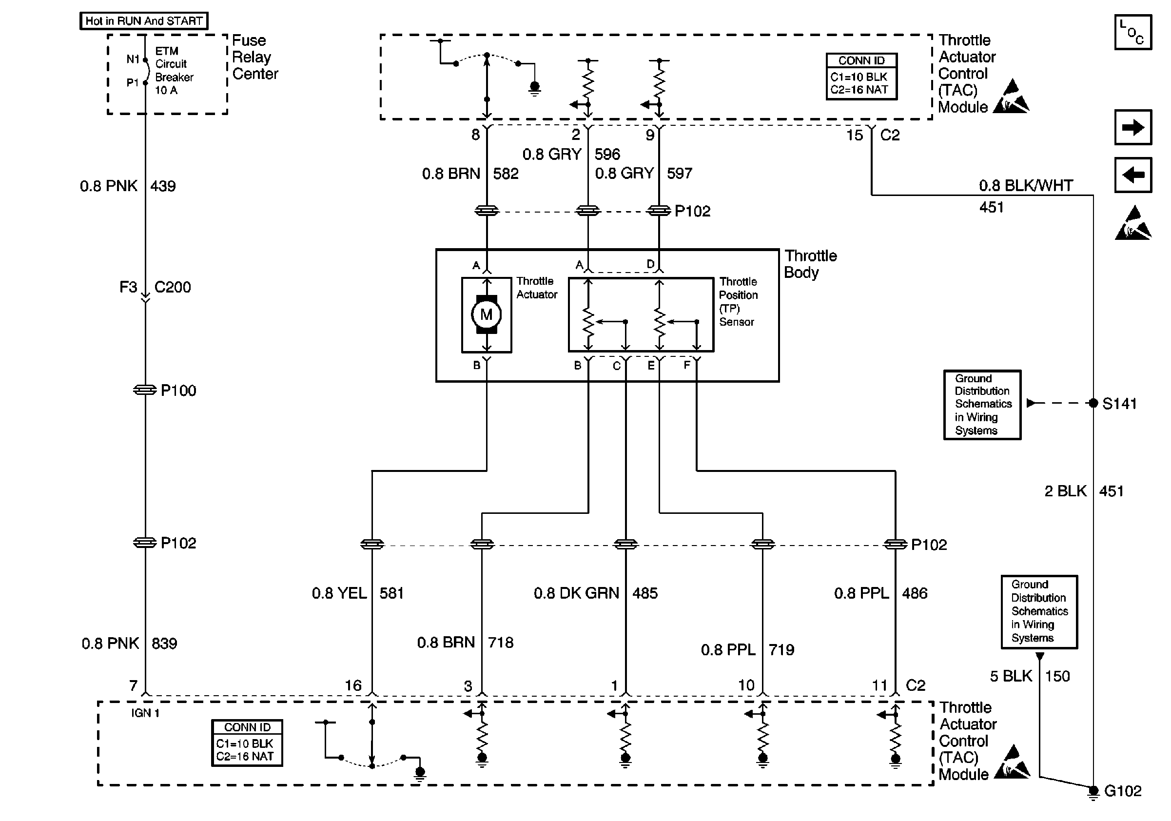
| Figure 12: |
TAC Module and Throttle Body
|
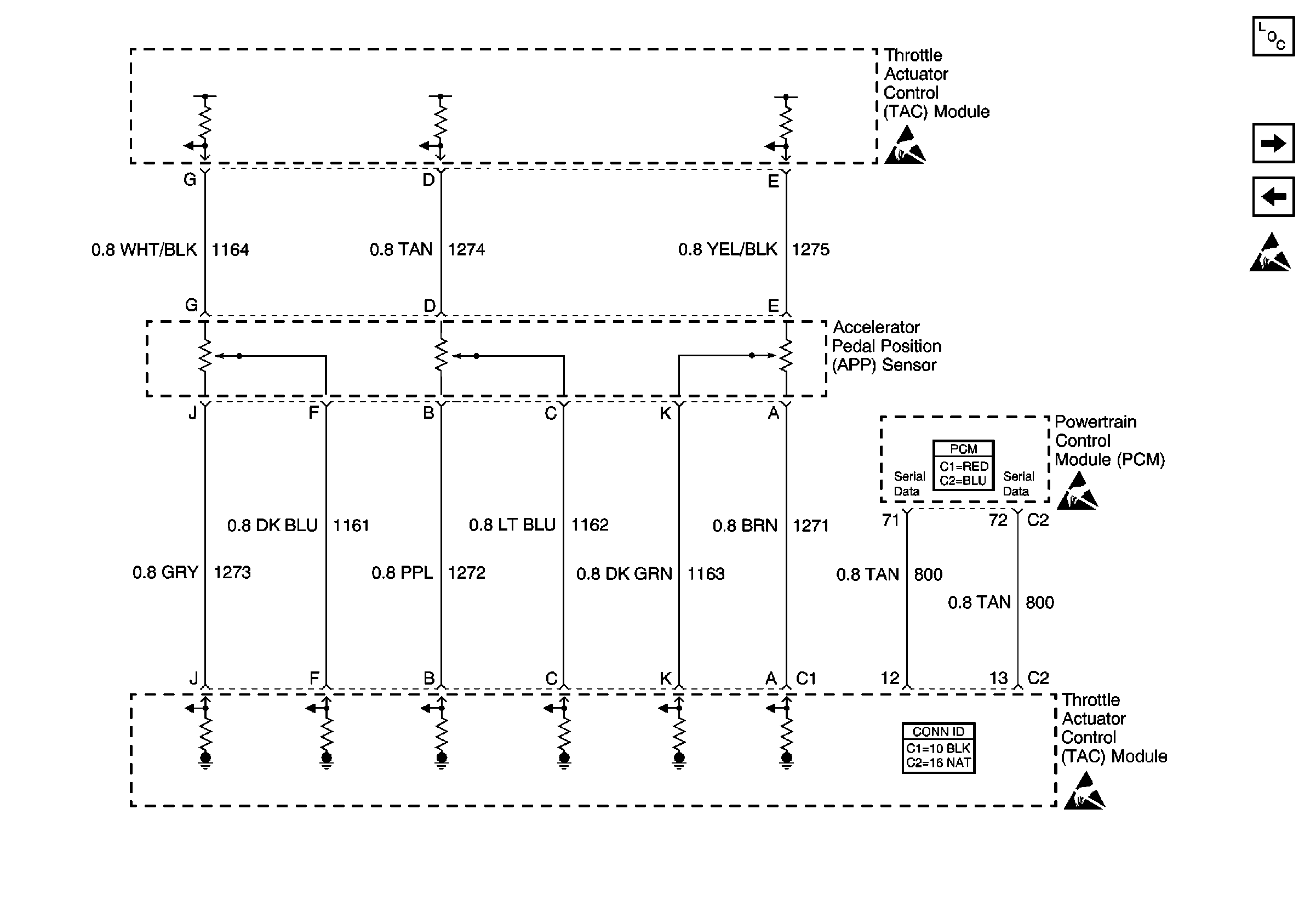
| Figure 13: |
APP Sensor and TAC Module
|
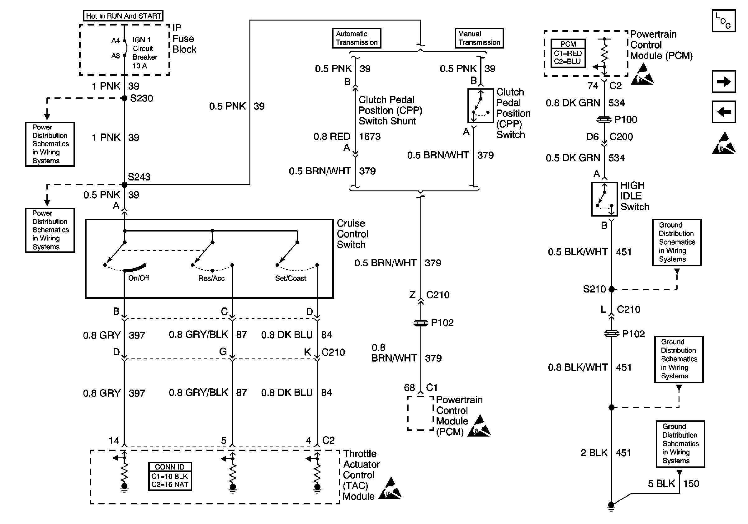
| Figure 14: |
CPP, Cruise Control And High Idle Switches
|
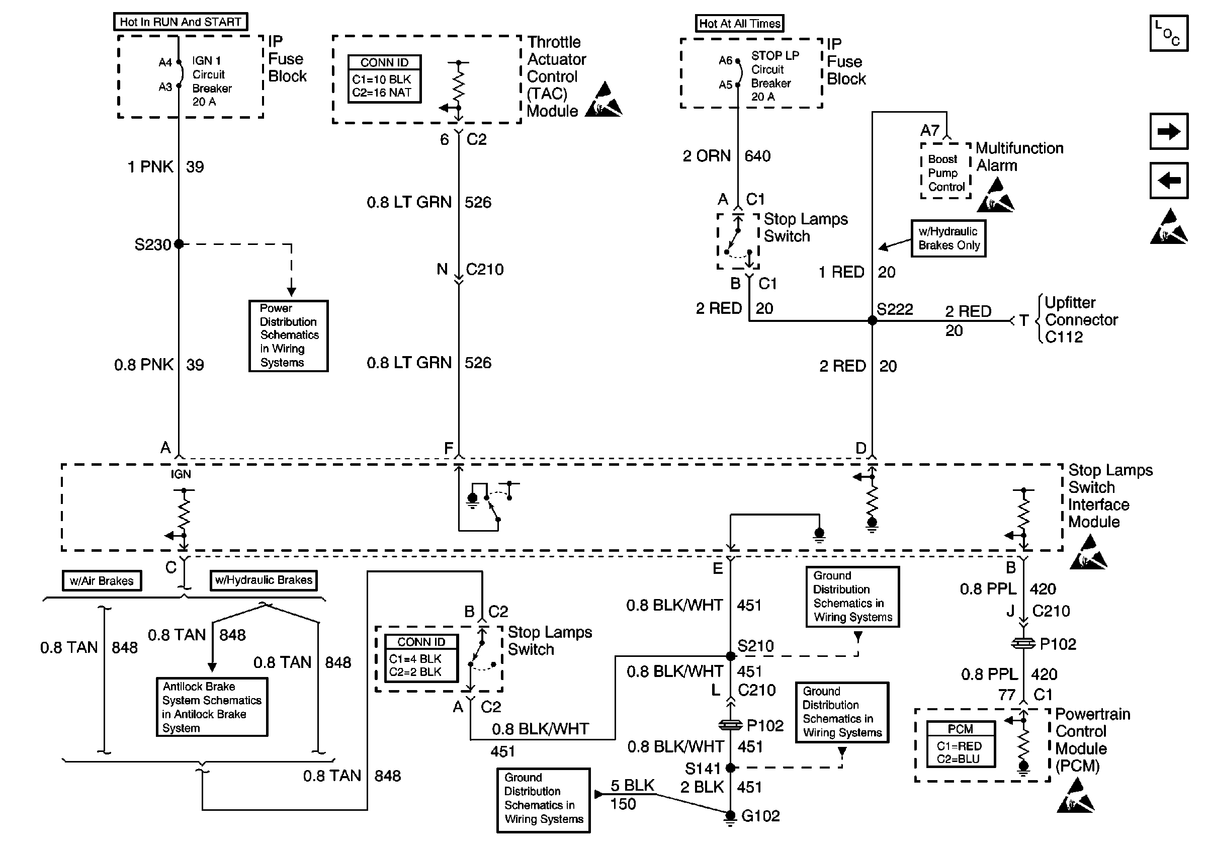
| Figure 15: |
Stop Lamps Switch Interface Module
|
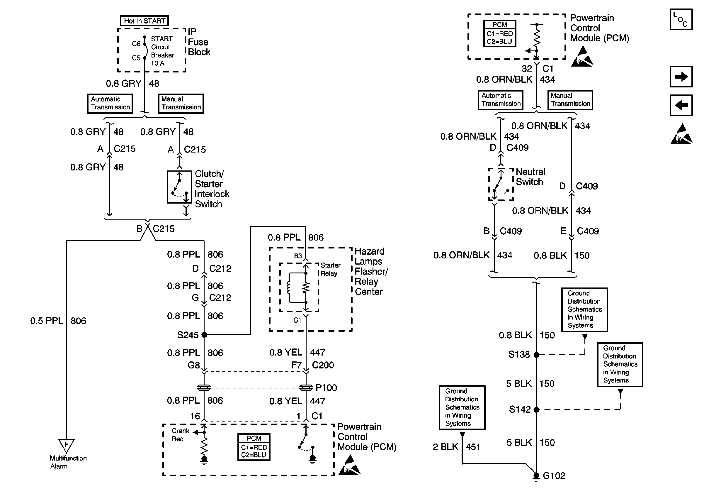
| Figure 16: |
Clutch/Starter and Neutral Switches
|
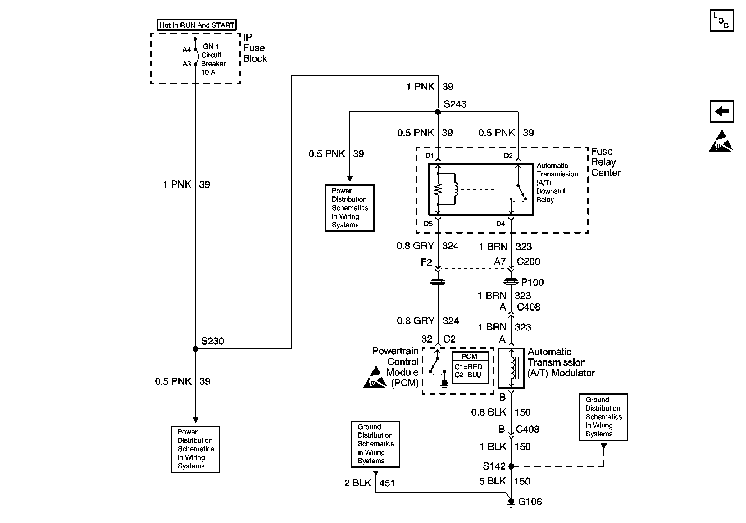
| Figure 17: |
Automatic Transmission Downshift
|


