Removal Procedure
- Disconnect the negative battery cables from the batteries. Refer to Battery Cable Replacement in Engine Electrical.
- Remove the hood from the vehicle. Refer to Hood Replacement in Body Front End.
- Remove the left and right wheel house panel from the vehicle. Refer to Wheelhouse Panel Replacement in Body Front End.
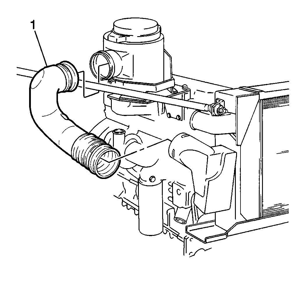
- Remove the air intake duct (1) from the from the air cleaner.
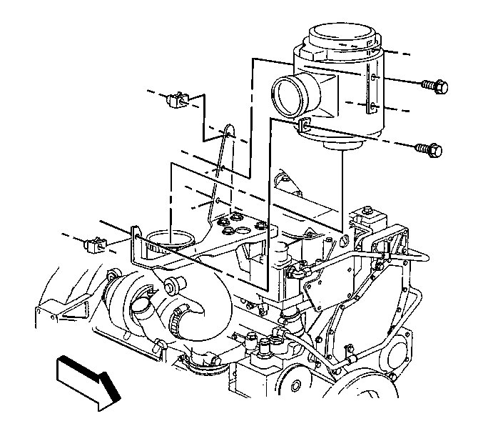
- Remove the air cleaner assembly from the mounting bracket.
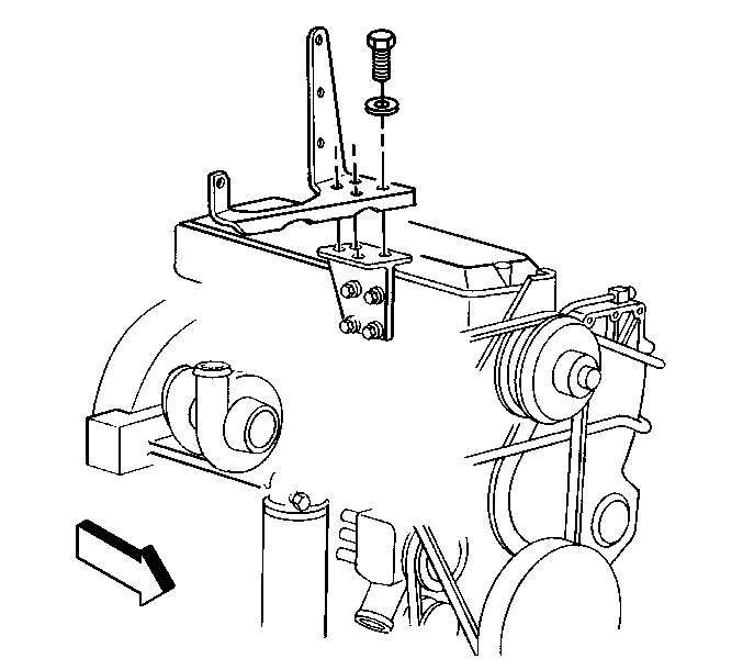
- Remove the air cleaner mounting bracket from the engine block.
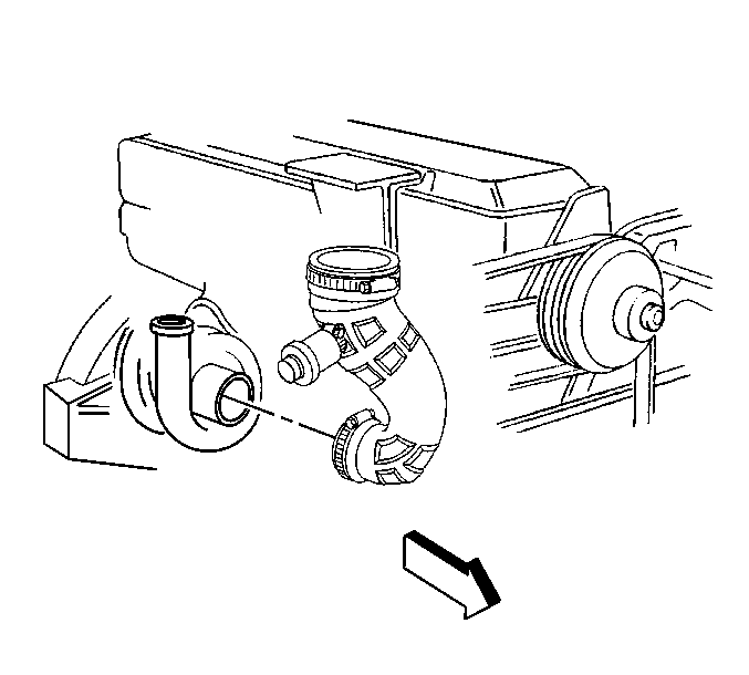
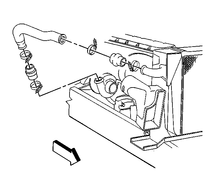
- Remove the air outlet duct between the turbocharger and the air cleaner housing.
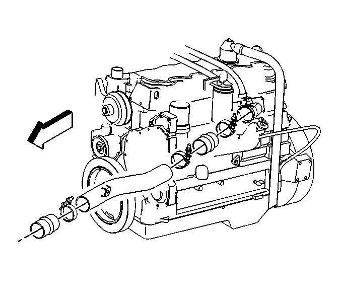
- Remove the outlet air duct between the turbochargers and the charged air cooler.
- Remove the charged air cooler outlet duct from charged air cooler and the intake manifold.
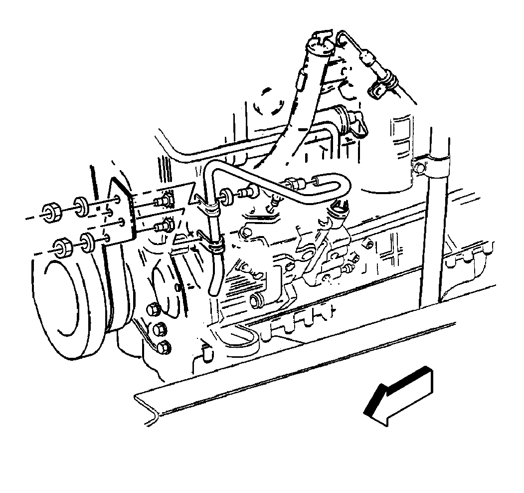
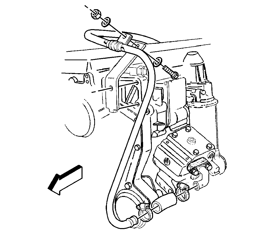
- Disconnect the power steering lines from the power steering pump and allow to drain in a suitable drain pan.
- Drain the crankcase. Refer to Caterpillar® 3126 Unit Repair Manual.
- Drain the engine cooling system. Refer to Cooling System Draining and Filling in Engine Cooling.
- Drain the air reservoirs for the air brakes. Refer to Draining Reservoirs in Air Brakes.
- Disconnect the discharge line from the air compressor.
- Remove the governor air line from the air compressor.
- Remove the air inlet line from the air compressor.
- Remove the engine wiring harness from the retainers (left side only).
- Disconnect the electrical connectors from the following items:
- Remove the electrical connectors from the following items:
- Remove the engine wiring harness from the retainers (right side only).
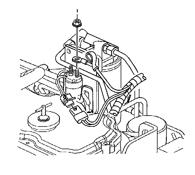
- Remove the electrical connectors from the heated air intake relay.
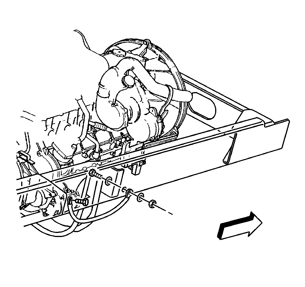
- Remove the ground strap from the frame to the starter.
- Remove the starter from the vehicle. Refer to Starter Motor Replacement in Engine Electrical.
- Secure the engine wiring harness out of the way.
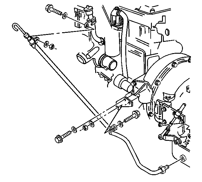
- Remove the transmission oil level indicator and the tube (AT 545 and MTS transmission).
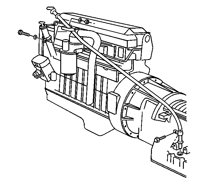
- Remove the transmission oil level indicator and the tube (MD series transmission).
- Remove the radiator from the vehicle. Refer to Radiator Replacement in Engine Cooling.
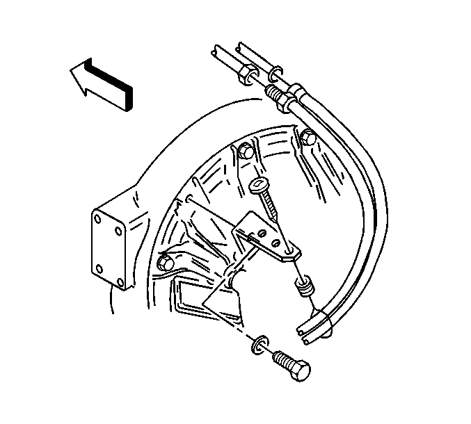
- Remove the transmission cooler lines from the retainer.
- Remove the transmission oil cooler lines from the retainer and secure out of the way.
- Remove the lower radiator panel from the vehicle. Refer to Radiator Lower Mounting Panel Replacement in Engine Cooling.
- Remove the radiator inlet hose from the engine assembly. Refer to Radiator Inlet Hose Replacement in Engine Cooling.
- Remove the radiator outlet hose from the engine assembly. Refer to Radiator Outlet Hose Replacement in Engine Cooling.
- Disconnect the exhaust pipe from the turbocharger.
- Remove the torque convertor bolts from the torque convertor.
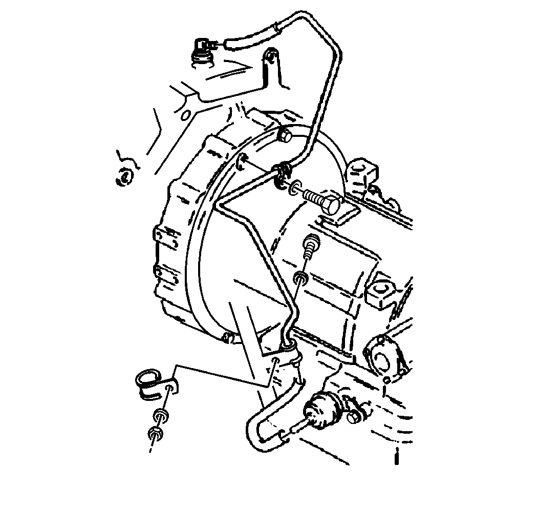
- Remove the vacuum modulator vacuum line (for automatic transmission only).
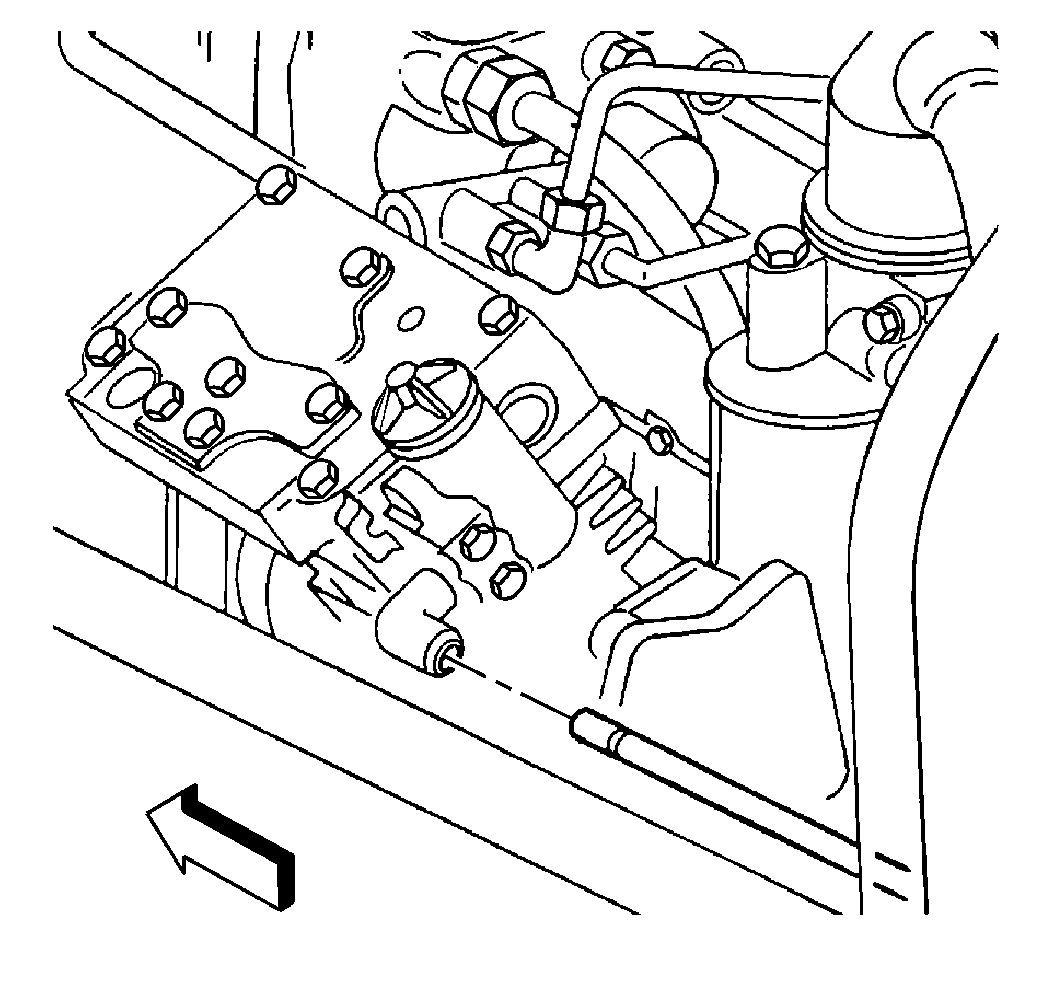
- Disconnect the fuel lines at the rear of the engine.
- Support the transmission with a suitable transmission support.
- Attach a suitable lifting device to the engine assembly.
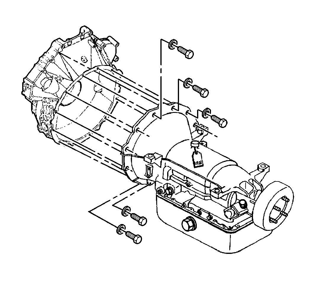
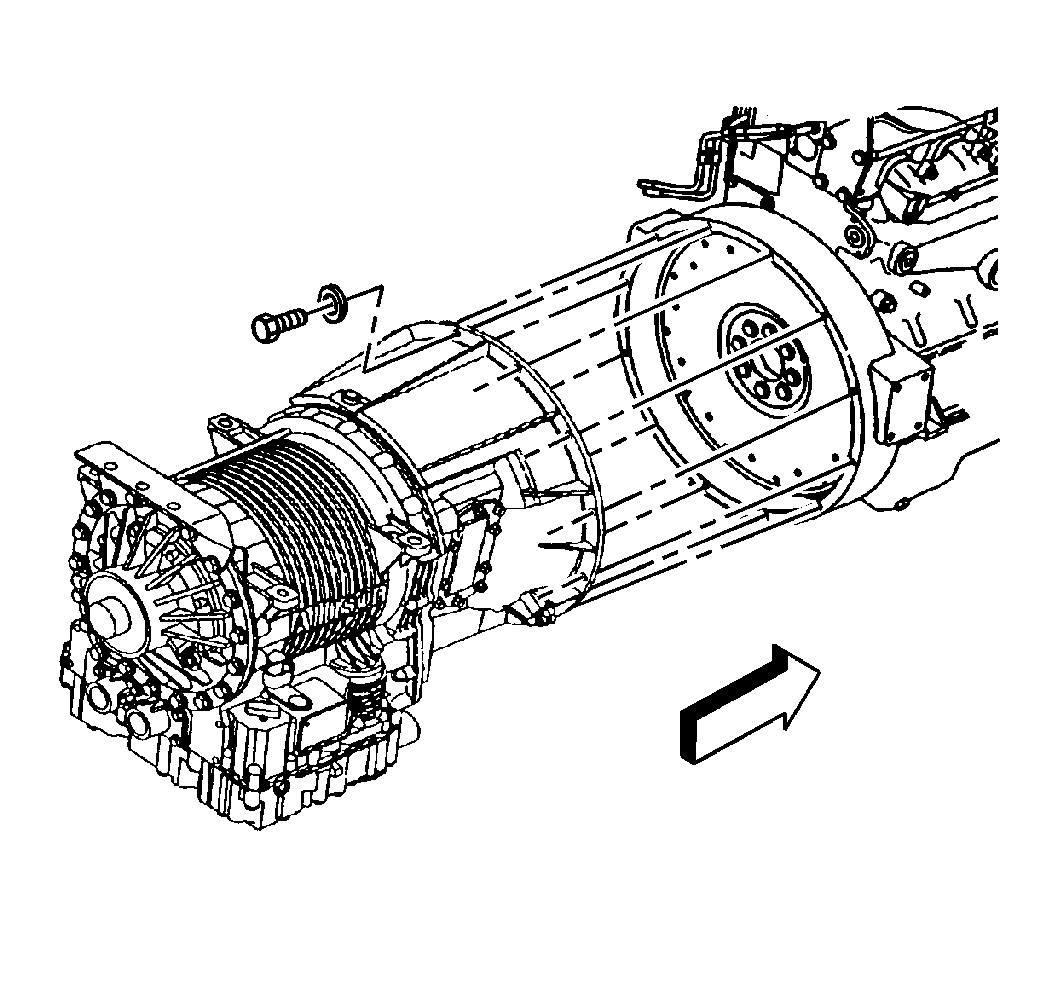
- Remove the bolts from the transmission to the engine block.
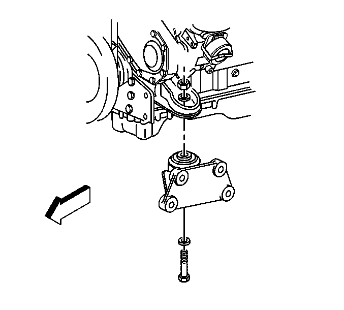
- Remove the engine mount through bolts from the engine mounts.
- Remove the engine from the vehicle.
- Remove the clutch (if equipped) from the flywheel. Refer to Clutch Assembly Replacement in Clutch.
- Remove the flywheel from the engine assembly. Refer to Caterpillar® 3126 Unit Repair Manual.
- Install the engine on a suitable engine stand.
- Remove the lifting device from the engine assembly.
Important: Cover the turbocharger openings with duct tape or any other suitable cover in order to prevent any foreign objects from falling into the turbocharger. This will prevent any damage from occurring to the turbocharger.
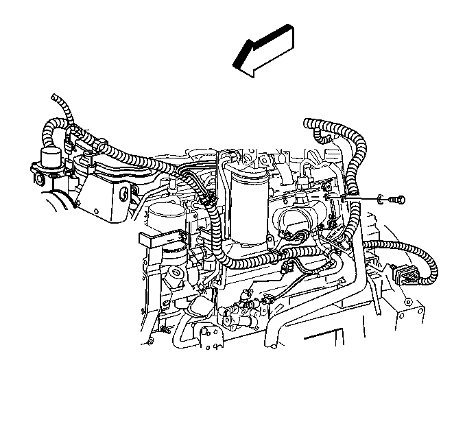
| • | oil pressure sensor |
| • | low oil pressure switch |
| • | E.C.U. (Engine Control Unit) |
| • | coolant temperature sensor |
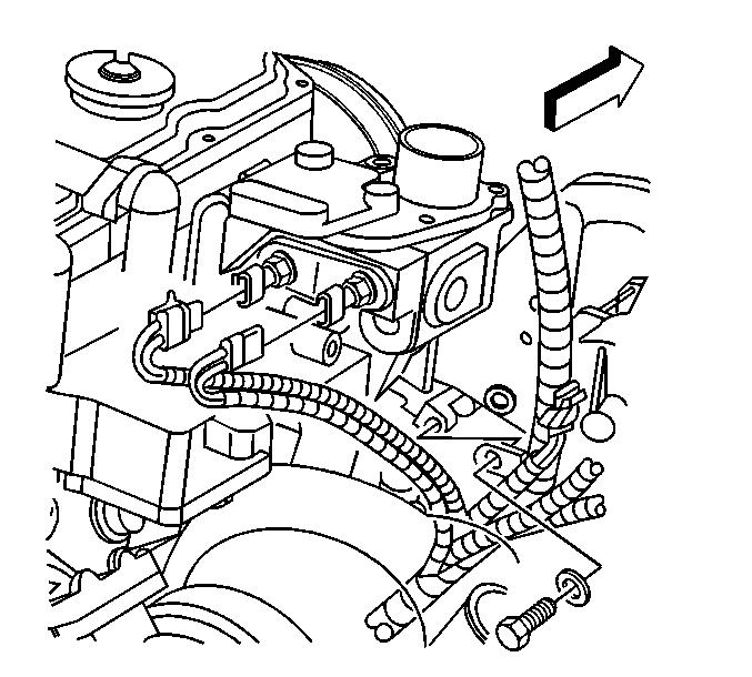
| • | shutdown switch |
| • | coolant temperature switch |
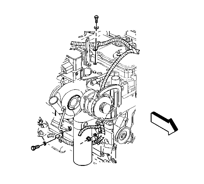
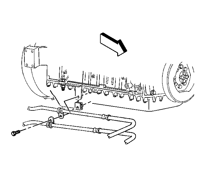
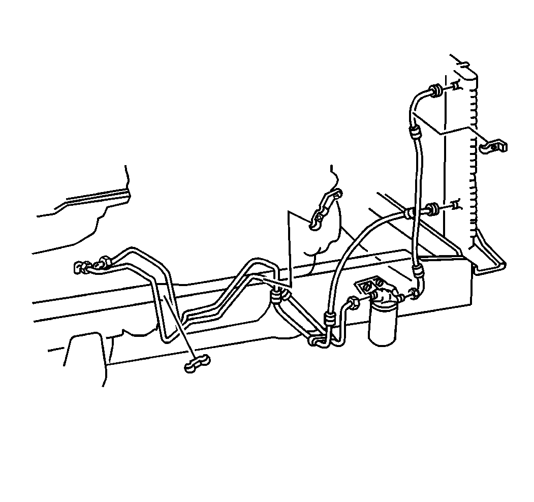
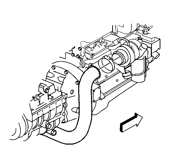
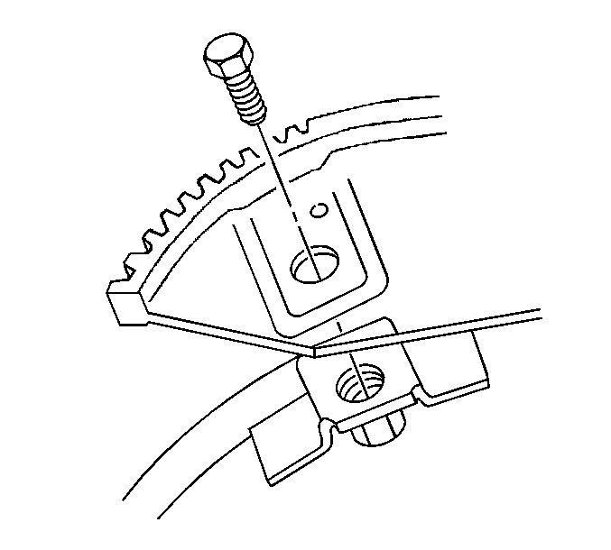
Important: It maybe necessary to remove the clutch or the flywheel from the engine assembly before installing the engine assembly on the engine stand.
Installation Procedure
- Install the lifting device to the engine assembly.
- Remove the engine assembly from the engine stand.
- Install the flywheel to the crankshaft. Refer to Caterpillar® 3126 Unit Repair Manual.
- Install the clutch (if equipped) to the flywheel. Refer to Caterpillar® 3126 Unit Repair Manual.
- Install the engine assembly in the vehicle.
- Install the bolts from the transmission to the engine block (manual transmission).
- Install the bolts from the transmission to the engine block (automatic transmission).
- Lower the engine on the front engine mount brackets.
- Install the engine mount through bolts.
- Remove the lifting device from the engine assembly.
- Remove the transmission support.
- Install the vacuum line for the modulator valve.
- Connect the fuel lines at the rear of the engine.
- Install the bolts from the flywheel to the torque convertor.
- Install the starter motor to the engine block. Refer to Starter Motor Replacement in Engine Electrical.
- Install the ground strap from the frame to the starter.
- Install the exhaust pipe to the turbocharger.
- Install the electrical connectors for the heated air intake relay.
- Install the wiring harness on the right front of the engine block to the retainers.
- Install the electrical connectors to the following items:
- Install the engine wiring harness to the retainers.
- Install the electrical connectors to the following items:
- Install the wiring harness to the retainers.
- Install the radiator inlet hose to the engine assembly. Refer to Radiator Inlet Hose Replacement in Engine Cooling.
- Install the radiator outlet hose to the engine assembly. Refer to Radiator Outlet Hose Replacement in Engine Cooling.
- Install the lower radiator panel in the vehicle. Refer to Radiator Lower Mounting Panel Replacement in Engine Cooling.
- Install the radiator in the vehicle. Refer to Radiator Replacement in Engine Cooling.
- Install the transmission lines to the retainer.
- Install the transmission oil level indicator and tube to the engine assembly (AT 545 and MTS transmission).
- Install the transmission oil level indicator and tube to the engine assembly (MD series transmission).
- Install the air inlet hose to the air compressor.
- Install the governor air line to the air compressor.
- Install the discharge air line to the air compressor.
- Install the lines to the power steering pump.
- Install the air cleaner housing mounting bracket to the cylinder head.
- Remove the covers from the turbocharger openings.
- Install the outlet duct from the charged air cooler to the intake manifold.
- Install the outlet duct from the turbocharger to the charged air cooler.
- Install the duct from the turbocharger to the air cleaner housing.
- Install the air cleaner housing to the mounting bracket.
- Install the duct (1) from the air cleaner to the air intake.
- Install the left and right wheel house panels to the vehicle. Refer to Wheelhouse Panel Replacement in Body Front End.
- Install the hood on the vehicle. Refer to Hood Replacement in Body Front End.
- Connect the battery negative cables to the batteries. Refer to Battery Cable Replacement in Engine Electrical.
- Fill the engine crankcase with the proper grade and type of engine oil. Refer to Approximate Fluid Capacities in Maintenance and Lubrication.
- Fill the cooling system with the proper type and quantity of engine coolant. Refer to Cooling System Draining and Filling .
- Fill the power steering reservoir to the proper level. Refer to Approximate Fluid Capacities in Maintenance and Lubrication.
- Fill the air brake reservoir with air. Refer to Filling Reservoirs in Air Brakes.
- Bleed the power steering if necessary.
- Prime the lubrication oil galleries if the engine has been rebuilt. Refer to Caterpillar® 3126 Unit Repair Manual.
- Prime the engine oil system if the engine has been rebuilt. Refer to Caterpillar® 3126 Unit Repair Manual.
- Prime the fuel system before starting the engine. Refer to Caterpillar® 3126 Unit Repair Manual.
Notice: Use the correct fastener in the correct location. Replacement fasteners must be the correct part number for that application. Fasteners requiring replacement or fasteners requiring the use of thread locking compound or sealant are identified in the service procedure. Do not use paints, lubricants, or corrosion inhibitors on fasteners or fastener joint surfaces unless specified. These coatings affect fastener torque and joint clamping force and may damage the fastener. Use the correct tightening sequence and specifications when installing fasteners in order to avoid damage to parts and systems.
Tighten
Tighten the bolts to 54 N·m (40 lb ft).
Tighten
Tighten the bolts to 58 N·m (43 lb ft).

Tighten
Tighten the through bolts to 54 N·m (40 lb ft).


Tighten
Tighten the torque convertor bolts to 67 N·m (49 lb ft).

Tighten
Tighten the retaining nuts to 27 N·m (20 lb ft).

Tighten
Tighten the retaining nut to 22 N·m (16 lb ft).

Tighten
Tighten the following items:
| • | Tighten the mounting bolts to 45 N·m (33 lb ft). |
| • | Tighten the retaining nuts to 22 N·m (16 lb ft). |

| • | shutdown switch |
| • | coolant temperature switch |
Tighten
Tighten the mounting bolt to 45 N·m (33 lb ft).

| • | oil pressure sensor |
| • | low oil pressure switch |
| • | E.C.U (Engine Control Unit) |
| • | coolant temperature sensor |
Tighten
Tighten the retaining bolts to 22 N·m (16 lb ft).

Tighten
Tighten the retaining bolt to 30 N·m (22 lb ft).

Tighten
Tighten the retaining bolt to 20 N·m (15 lb ft).

Tighten
Tighten the retaining bolt to 20 N·m (15 lb ft).


Tighten
Tighten the mounting bolts to 10 N·m (89 lb in).


Tighten
Tighten the mounting bolts to 45 N·m (33 lb ft).

| • | For vehicles equipped with the remote reservoir, refer to Power Steering System Bleeding in Power Steering. |
| • | For vehicles equipped with the integral reservoir, refer to Power Steering System Bleeding in Power Steering. |
