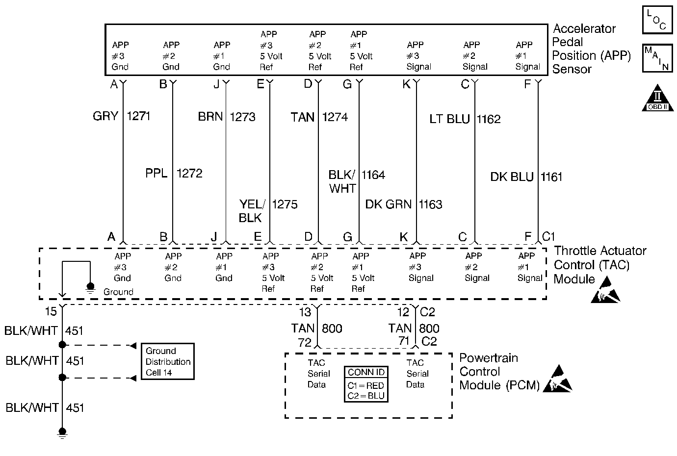
Circuit Description
The Accelerator Pedal Position (APP) sensor is mounted on the accelerator
pedal assembly. The sensor is actually three individual Accelerator Pedal
Position sensors within one housing. Three separate signal, ground
and 5.0 volt reference circuits are used to connect the Accelerator
Pedal Sensor assembly and the Throttle Actuator Control (TAC) Module.
If only one APP sensor DTC is set, the redundant APP systems allow
the Throttle Actuator Control (TAC) system to continue operating
normally. This DTC sets if the PCM detects a problem with more than
one APP sensor. One APP sensor DTC will not cause the Reduced Engine
Power message to be displayed. Two APP sensor DTCs for the same
sensor also will not cause the Reduced Engine Power message to be
displayed. However, if two or more DTCs are set involving more than
one APP sensor, this DTC will set. The Reduced Engine Power message
is displayed.
Conditions for Running the DTC
| • | DTCs P1517, P1518 are not set. |
| • | Ignition switch in the crank or run position. |
| • | Ignition voltage greater than 5.23 volts. |
Conditions for Setting the DTC
| • | Two or more APP sensors are out of range or all three APP sensors
disagree or one APP sensor is out of range and the other two APP sensors disagree. |
| • | All above conditions met for less than 1 second. |
Action Taken When the DTC Sets
| • | The PCM will illuminate the Malfunction Indicator Lamp (MIL) and
the Reduced Engine Power light will be on when the diagnostic fails. |
| • | The PCM will record operating conditions at the time the diagnostic
fails. This information will be stored in the Freeze Frame and/or Failure
Records. |
| • | If no other TAC System DTCs are set, the TAC System will operate
in Reduced Engine Power mode, and this DTC will be stored. If certain TAC
System DTCs are set at the same time, the TAC System will either
default to a more tightly restricted mode of operation if it is
determined that limited safe operation is possible, or command engine
shut down. |
Conditions for Clearing the MIL/DTC
| • | The PCM will turn the MIL off after three consecutive drive trips
that the diagnostic runs and does not fail. |
| • | A History DTC will clear after forty consecutive warm-up
cycles, if no failures are reported by this or any other emission related
diagnostic. |
| • | A last test failed (Current DTC) will clear when the diagnostic
runs and does not fail. |
| • | PCM battery voltage is interrupted. |
| | Important:: The clear DTC info function may have to be performed twice in order
to clear a Throttle Actuator Control System DTC.
|
Diagnostic Aids
An intermittent may be caused by the following:
| • | Poor connections -- Check for adequate terminal tension.
Refer to
Wiring Repairs
in Wiring Systems. |
| • | Rubbed through wire insulation. |
| • | Broken wire inside the insulation. |
| • | Inspect the TAC module connectors for signs of water intrusion.
When this occurs, multiple DTCs should be set and no circuit or component
problems can be located. |
| • | Refer to Intermittents under service category
Symptoms
. |
| • | If a repair is completed and the DTC was cleared using a scan
tool on the same ignition cycle, the default action will not clear until an
ignition cycle has occurred. |
Test Description
The numbers below refer to the step numbers on the diagnostic table.
-
When the problems are corrected which are causing the APP sensor DTCs
to set, the status of this DTC will change to History.
When the TAC module detects a problem within the TAC System, more than
one TAC System related DTC may set. This is due to the many redundant tests
run continuously on this system. Locating and repairing one individual problem
may correct more than one DTC. Keep this in mind when reviewing captured
DTC info.

